26
27
27
28
29
30
28
31
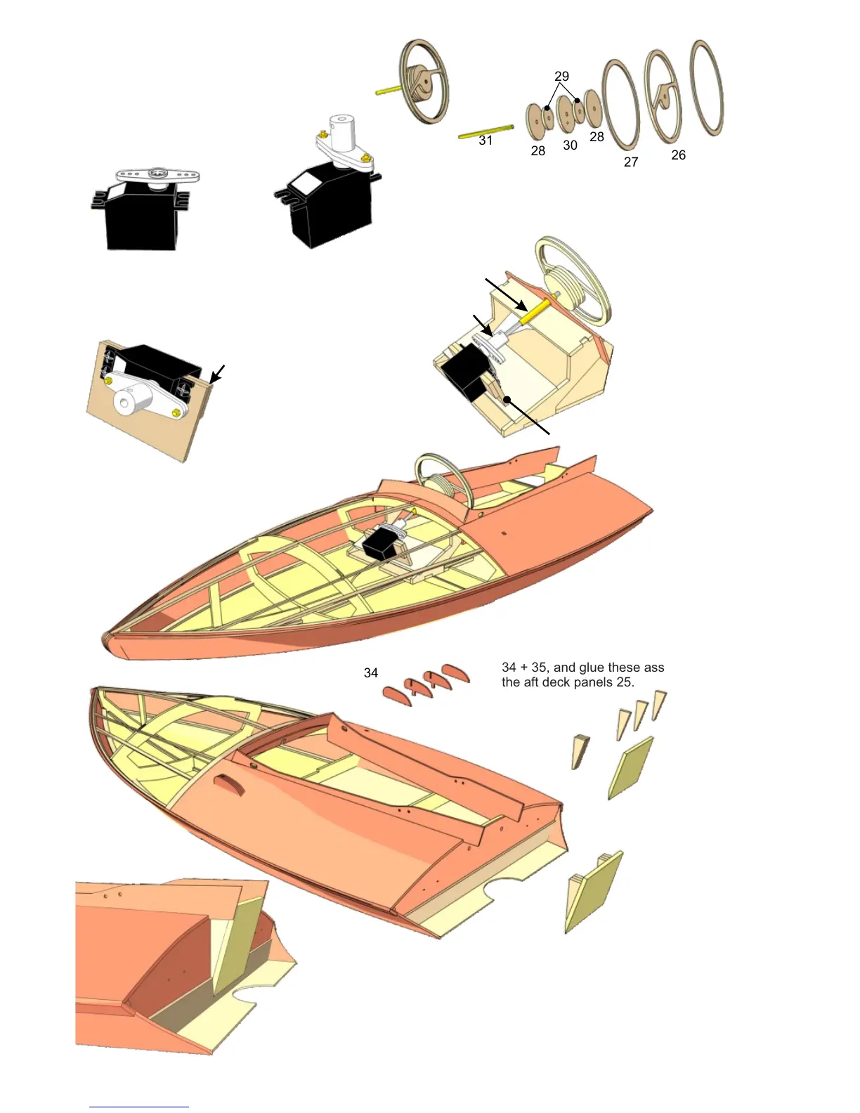
Roughen the steering column over a length of
9 mm with abrasive paper, then assemble the
steering wheel - consisting of parts 26 to 30 -
using two-pack adhesive.
32
Set the servo to centre,
and fit the output arm on
the servo shaft in the
position shown.
Turn the output arm
through 90°, and fix the
aluminium coupler 32 to
it using the screws 32.1.
33
33.1
Glue the doublers 33.1 to the
rear face of the servo plate
33, and screw the servo to it.
Insert the servo / servo
plate assembly in the slot
of part 21, slip the shaft 31
(with the steering wheel)
through the brass bush
and into the coupler 32,
and align the parts
carefully. Parts 21 and 33
can now be glued together.
Carefully slide the whole
assembly into position in
the hull, and leave it there
until the glue has set hard.
21
22
32
33
Assemble the pulley brackets from parts
34 + 35, and glue these assemblies in
the aft deck panels 25.
34
35
34
39
39.1
40
40
41
25
Glue the transom 39
and the transom
reinforcement 39.1 in
place. Sand the bottom
edge at an angle over a
width of 10 mm as
indicated. Assemble the
brackets 40 in sets of
three, and glue them to
the motor mount 41.
Glue the motor mount assembly 40 + 41 to parts 39
and 39.1 using two-pack adhesive. Fit two screws
43 through frame 1 and the transom 39 from the
inside for additional strength.
14
15
16
17
18
20
21
19
39.1
41
39
40
41
22
The whole model should now be given several coats
of waterproof lacquer until the desired surface
quality is achieved.