WALL PACK SERIES
SEMI CUT-OFF WALL PACK LUMINAIRE
INSTALLATION MANUAL
www.spitzerlighting.com
702 Interchange Blvd., Newark, DE 19711 Specication is subject to change without notice
2/2
STEP BY STEP - WARNING: TURN OFF THE POWER AT FUSE OR CIRCUIT BOX.
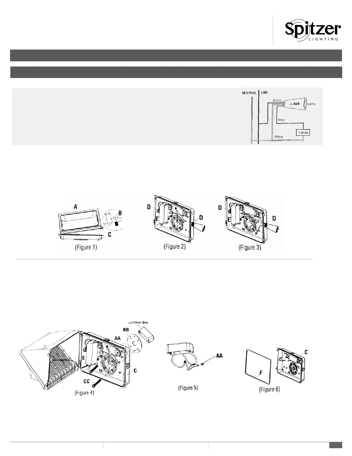
1. Loosen 2 pcs set screws (Part B) and open the upper cover plate of the xture (Part A) slowly. (Figure 1)
2. Fix photoelectric switch to the product (Figure 2)
3. Loosen (Part AA), Connect the wiring of photoelectric switch to the product by using the Wire Nuts (Part AA) to secure wiring connection. (Figure 3)
(N wire connect to N wire, L wire connect to L wire)
INSTALLATION
PHOTOELECTRIC SWITCH JL-404 INSTALLATION
Disconnect power, remove junction box cover, place the SWITCH in knockout hole and fasten with locknut.
Wire according to the diagram in right hand.
Do not install the switch with the Photocell facing articial or reected light. This will cause the unit to
cycle on and off at night.
4. Drill 2 holes on the pedestal of the xture (Part C). (Figure 1)
5. Start Machine Screws (Part CC) to tighten the pedestal of the xture (Part C) with the Gasket (Part BB). (Figure 1)
6. Make wire connections in accordance with local codes by using the Wire Nuts (Part AA) to secure wiring connection. (Figure 5)
a. Connect the HOT wire (black) from the main source to the BLACK wire from the power suppy (Part E.)
b. Connect the NEUTRAL wire (white) from the main source to the WHITE wire from the power supply (Part E)
c. Connect the GROUNDING wire (green/yellow? from the main source to GROUND wire (green/yellow) from the power supply (Part E)
7. Close the uppper cover plate of the xture (Part A) slowly and tighten 2 pcs set screws (Part B) (Figure 1)
8. Turn on the power at fuse or circuit box.
CAUTION:
1. DO NOT OVERSPREAD THE PHOTOCELL CONTROLLER (PART D).
2. ENSURE THE WATERPROOF RUBBER GASKET (PART F) IS ASSEMBLED IN PLACE. (FIGURE 6)
 Loading...