Do you have a question about the SPL Dynamics ICE-150.4 and is the answer not in the manual?
High sound levels can cause hearing loss and impair driving safety by blocking external sounds.
Proper mounting ensures heat dissipation and optimal cooling. Avoid enclosing the amplifier to allow airflow.
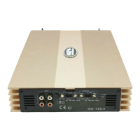
Connect speakers correctly to plus/minus terminals using AWG 15# cable.
Connect the +12V power cable with an in-line fuse near the battery terminal.
Connect remote cable to source unit for automatic amplifier on/off.
Connect chassis ground cable tightly to a massive, conductive place.
Matches amplifier sensitivity to source unit output for clear music.
Use car audio RCA cables, keep them short, and avoid routing near car electronics.
Controls filter modes for speaker output frequencies.
Buffered output signal for daisy-chain amplifier installation.
LED indicates proper operation; flashes/shuts down on malfunction.
LED indicates fault/shutdown for protection against damage.
Selects 2-channel or 4-channel input mode for the ICE-150.4.
Protects amplifier from overcurrent; do not use a higher amp fuse.
Steps for choosing a location, mounting, and connecting the amplifier.
Diagram showing input connections for the ICE-150.2 amplifier.
Wiring diagram for bridging the ICE-150.2 amplifier for a 4 ohm woofer.
Wiring diagram for the ICE-150.4 amplifier in a 4 ohm 4 channel setup.
Check connections, battery cables, fuses, and remote voltage.
Check volume, gain, RCA, and speaker connections.
Check RCA/speaker connections, source balance, or speaker damage.
Check ground, terminals, battery voltage, and remote wire.
Check source and amplifier gain settings, or speaker condition.
Check for speaker short/damage, overheating, overload, or low battery.
| Channels | 4 |
|---|---|
| RMS power at 4 Ohms | 150W x 4 |
| RMS power at 2 Ohms | 230W x 4 |
| RMS power at 4 Ohms Bridged | 460W x 2 |
| Frequency Response | 10Hz - 30kHz |
| Signal-to-Noise Ratio | >90dB |
| THD | <0.1% |
| Crossover | High Pass / Low Pass |