M
Monica JohnstonJul 31, 2025
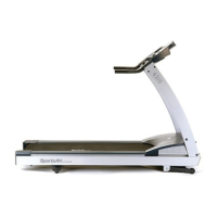
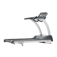
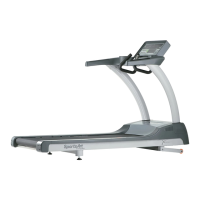
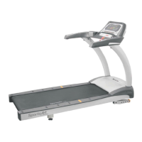
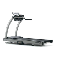
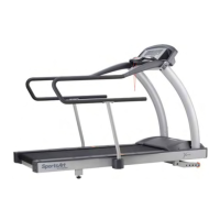
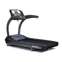
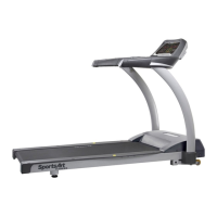
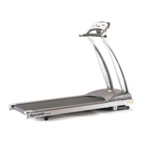
What to do if SportsArt Fitness 6200 HTR handlebar is not functioning?
- SSabrina AdamsJul 31, 2025
If the SportsArt Fitness Treadmill HTR handlebar isn't working, check the HTR handlebar wire for any shorts or breaks. Also, while holding the HTR handlebar, examine the HTR board. If the D4 indicator doesn't light up and stay lit, and the D5 indicator doesn't flash afterward, then the HTR handlebar or wire might be faulty.