


C
crystalcarneyJul 31, 2025
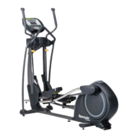
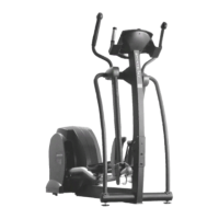
What to do if the generator F1 2-amp fuse is blown on my SportsArt Fitness 8300?
- LLindsay AndersonJul 31, 2025
If the generator F1 2-amp fuse on the drive board of your SportsArt Fitness Elliptical Trainer is blown, disconnect the generator wire connector nearest the generator.