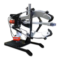
The device described in the manual is a 100-TON and 200-TON Hydraulic Puller System, designed for heavy-duty pulling applications. These systems are used to remove components such as gears, pulleys, wheels, sleeves, and other press-fit parts. The manual details various models within both the 100-TON and 200-TON categories, including single-acting and double-acting hydraulic pullers, and a 200-TON hydraulic puller system.
Function Description:
The hydraulic puller system utilizes hydraulic power to generate significant force, enabling the safe and efficient removal of tightly fitted components. The system consists of a main frame (cage), jaws, jaw tips, a pushing adaptor, a cage cylinder, a pushing cylinder, control valves, a hoist cylinder, a mast, a base, and casters. The hydraulic cylinders extend to push against the shaft, while the jaws grip the component to be removed, pulling it off the shaft. The system can be configured with either two or three jaws, depending on the model and application requirements. Double-acting models offer both extension and retraction of the cylinder, providing more control during operation. The hoist cylinder and mast facilitate easy positioning and adjustment of the puller system.
Important Technical Specifications:
The manual provides detailed product data for various models, including:
100-TON Hydraulic Puller Systems:
- Capacity: 100 tons (890 kN)
- Number of Jaws: 2 or 3
- Spread (A): 7.5 to 70 in. (191 to 1778 mm)
- Overall Length (B): 77 in. (1956 mm)
- Reach (C): 50 in. (1270 mm)
- Jaw Length (D): 53 in. (1346 mm)
- Jaw Tip Width (E): 1.25 in. (32 mm)
- Tip Clearance (F): 3.5 in. (89 mm)
- Tip Depth (G): 3.5 in. (89 mm)
- Weight: Ranges from 1700 lbs (771 kg) for 2-jaw single-acting to 2050 lbs (930 kg) for 3-jaw double-acting.
200-TON Hydraulic Puller System:
- Capacity: 200 tons (1770 kN)
- Number of Jaws: 4
- Spread (A): 6.5 to 70 in. (203 to 1778 mm)
- Overall Length (B): 78.5 in. (1994 mm)
- Reach (C): 48 in. (1219 mm)
- Jaw Length (D): 53 in. (1346 mm)
- Jaw Tip Width (E): 1.25 in. (32 mm)
- Tip Clearance (F): 3.5 in. (89 mm)
- Tip Depth (G): 3.5 in. (89 mm)
- Weight: 4150 lbs (1882 kg)
Couplers:
- PTHT-1164: 4.00 in. (102 mm) diameter, 9.50 in. (241 mm) length.
- PTHT-1163: 4.00 in. (102 mm) diameter, 19.00 in. (483 mm) length.
- PTHT-1162: 4.00 in. (102 mm) diameter, 29.00 in. (737 mm) length.
- Couplers are used with 200-TON pullers and have a diameter of 4 inches.
Jaw Tips:
- Available for 100 and 200 Ton puller models.
- PTHT-1180: standard with all models.
- PTHT-1180A: optional, for operations with limited space constraints.
- PTHT-1180S: optional, for operations with limited space constraints.
- Tip widths are 3 inches thick.
Usage Features:
- Adjustments: The manual outlines several adjustments to optimize the puller's performance:
- Raising/Lowering the Puller: Achieved by manipulating the hoist cylinder control valve.
- Hoist Travel Speed: Controlled by a restrictor valve, allowing adjustment of the puller descent rate.
- Changing Jaw Spread: The jaw spread can be adjusted by removing or adding cap screws, lock washers, and nuts on the jaw guide. Different jaw guide positions (default, increased spread, decreased spread) are illustrated.
- Adjusting Jaw Tips: Jaw tips should be turned 1-1/4" cap screw to maximize pulling surface and ensure correct alignment. Incorrect alignment can lead to damage.
- Adjusting Slide Rollers: Lowering the slide and puller assembly onto the base, loosening the hex bolt, moving rollers on each side, adjusting equal spacing between mast and slide tube, tightening the locking nut, and tightening the hex bolt.
- Operation:
- Setup: Transporting the puller by forklift, lining up the puller to the workpiece, and opening the jaws.
- Opening/Closing the Jaws: Involves placing the cylinder control valve in "Oil Supply" or "Jaw Open" position and activating the pump.
- Pulling an Object: Extending the cylinder ram towards the workpiece by placing the cylinder control valve in "Extend" position and activating the pump.
- Retracting Cylinder: Placing the cylinder control valve in the "Retract" position and activating the pump.
- PTPH-123T Transformation: Specific instructions are provided for transforming the PTPH-123T model, including starting in a 2-jaw configuration, moving the cage cylinder, removing the jaw from the left 2-jaw position, placing the jaw into the lower 3-jaw position, and placing the jaw from the left 2-jaw position into the upper 3-jaw position.
- Spread Range Diagram: A detailed diagram illustrates the jaw-opening spread ranges for both 100-TON and 200-TON hydraulic puller systems, showing how the jaws grip components of various sizes.
Maintenance Features:
- Safety Precautions: Emphasizes the importance of identifying safety symbols and understanding warnings (Danger, Warning, Caution, Important) to prevent personal injury and property damage.
- General Safety:
- Visually inspect all components for shipping damage.
- Ensure all repairs and replacement costs resulting from damage are covered by warranty.
- Predict the exact force needed for every pulling situation.
- Follow all safety precautions and warnings.
- Ensure all system components are protected from external sources of damage.
- Wear appropriate personal protective equipment (face shield, goggles, gloves, apron, hard hat, safety shoes, hearing protection).
- Verify that safety-related decals are installed, maintained, and replaced if they become hard to read.
- Keep hands away from possible pinching points.
- Use only genuine POWER TEAM replacement parts and endorsed hydraulic components.
- Hydraulic Puller System Specific Safety:
- Do not touch or handle hydraulic hoses or fittings with pressure in the system.
- Do not make any electrical adjustments with electrical power active.
- Do not make or break any hydraulic connections with pressure in the system.
- Do not overload the equipment.
- Do not stand on, under, or near the puller while in use.
- Avoid personal injury and equipment damage; maintain the maximum hydraulic pressure of 700 bar (10,000 psi).
- Check to ensure that all cylinders and components are securely fastened.
- Inspect puller for dents, cracks, or excessive wear before each use.
- It is recommended to use a 3-jaw puller whenever possible for more secure grip and better stability.
- Cover the application with a protective blanket before applying force.
- Use hydraulic gauges in each hydraulic system to indicate safe operating loads.
- Apply force gradually.
- Select the appropriate ram extender for each application.
- Always place the puller in the lowest position and remove ram extenders while transporting.
- Keep slide rollers and mast clean and lubricated.
- Always keep puller hoist vertical and the control valve closed when not adjusting vertical position.
- A small amount of oil seepage is normal from the breather vent on the hoist cylinder.
- Maintenance: Always clean the puller after use and store it in a clean, dry place.
- Shipping and Assembly: Ensure that shipping crate firmly rests on level ground, open small side panel, remove remainder of plywood, inspect puller for damage, save bolts for bracing the cart, inspect hoses for proper ratings, and fill reservoir with pump manufacturer specified oil.