Waukesha Cherry-Burrell Brand W60/W80 Valves Maintenance
08/2018 95-03022 Page 35
Air-to-Lower Actuator
1. Remove the lower body clamp (Figure 25, item 5) and the
lower body.
2. Remove the body o-ring (item 6); replace as needed.
3. If necessary, remove the lower bearing carrier (item 11) from
the lower body.
4. Remove the body o-ring (item 6) and stem o-ring (item 4)
from the bearing carrier; replace as needed.
5. Inspect and replace the PTFE bearing (item 2) as needed.
6. Apply air to Port B to lower the stem.
7. Using 5/8-inch wrench flats on the stem, unscrew and
remove the lower valve stem (Figure 25, item 7b).
8. Replace the o-ring (Figure 25, item 9) in the counter bore of
the lower stem as needed.
9. Replace the lower seat ring (Figure 25, item 8) as needed.
See “Seat Replacement” on page 37.
10. Release the air pressure.
11. Shut off the air and disconnect the air line to the actuator.
12. For valves with control modules, disconnect/lockout the
electrical power to the valve.
13. Remove the middle body clamp (item 5) and the middle body.
14. Remove the middle body o-ring (item 6); replace as needed.
15. Remove the upper body clamp (item 5) and the upper body
from the adapter (item 3).
16. Using 5/8-inch wrench flats on the stem, unscrew and
remove the upper valve stem (item 7a).
17. Replace the seat ring (item 8) as needed. See “Seat
Replacement” on page 37.
18. Unscrew the adapter (item 3) from the yoke.
19. Remove the body o-ring (item 6) and stem o-ring (item 4)
from the adapter; replace as needed.
20. Inspect and replace the PTFE bearing (item 2) as needed.
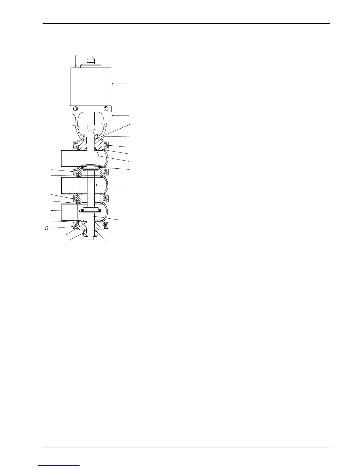
Figure 26: W65/W85 Divert Valve
VA100-245b
3,3a,
3b,3d
6
5
6
6
5
8
4