Do you have a question about the SPX Hankison Trip-L-Trap 505 and is the answer not in the manual?
Essential precautions for handling pressurized equipment and avoiding over-pressure.
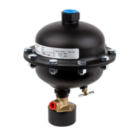
Automatic liquid drain for compressed air systems, used with various components.
Steps to prepare the drain, including removing thread protectors and installing fittings.
Guidelines for installing the drain line, including disposal and avoiding obstructions.
Details on when and how to install vent lines for proper drain operation.
Instructions for connecting the inlet line, ensuring downward slope and adequate size.
How the float and magnet mechanism controls the pilot valve for condensate discharge.
Mechanism of how compressed air drives the piston to open the discharge port.
Procedure for manually draining and depressurizing the unit.
Recommended monthly flushing to remove sludge and dirt for optimal performance.
Steps for disassembling, inspecting, and servicing the drain annually.
Detailed steps for disassembling and reassembling the drain's internal components.
Causes and corrective actions for continuous air discharge when the drain is stuck open.
Causes and actions for when condensate isn't discharged but can be manually drained.
The Trip-L-Trap® Automatic Condensate Drains, Models 505 and 506, are pilot-actuated, pneumatically operated devices designed for the automatic discharge of collected liquids from compressed air systems. These drains are recommended for use with various components of a compressed air system, including air receivers, drip legs, aftercoolers, separators, dryers, and filters, ensuring efficient removal of condensate without loss of air.
The core function of the Trip-L-Trap drains is to provide positive discharge of condensate. The operation is level-actuated and pilot-controlled. As condensate accumulates within the drain housing, a float, held in place by a magnet, begins to rise. When the condensate level reaches a sufficient height, the buoyancy of the float overcomes the magnetic holding force, causing the pilot valve to trip open.
Once the pilot valve opens, compressed air is directed into an air cylinder, which forcefully moves a piston. This action opens a large discharge port, allowing the accumulated condensate to be expelled from the system. After the condensate has been discharged, the float drops, and the pilot valve closes. The compressed air within the piston cylinder then bleeds off through a designated bleed hole. Air pressure within the housing subsequently moves the piston back to its original position, closing the discharge port securely and holding it shut until the next cycle of operation. This ensures that condensate is discharged efficiently while minimizing air loss. All models also feature a manual drain for depressurization and manual condensate discharge.
The Trip-L-Trap drains are designed for vertical installation to ensure proper float operation. For optimal performance, the inlet line should slope downward towards the drain inlet, allowing condensate to flow into the drain by gravity. The use of strainers is recommended to protect the drain from particulate contamination, and isolation valves can facilitate quick and easy servicing. It is crucial that the inlet pipe to the drain is not smaller than the inlet connection to prevent restricted drainage or "pockets" where condensate could accumulate.
A drain line is typically recommended to prevent condensate from spraying into the surrounding area. This line, which can be tubing (minimum 3/8" O.D.) or piping (minimum 1/4"), should be routed to an adequate sump or floor drain, preferably below the level of the drain. It is important not to obstruct the drain line with valves or severe bends, as this can impede condensate discharge. Since condensate is discharged at system pressure, the drain line should be anchored to prevent movement.
Vent lines are required for all bottom connection drains and for top connection drains where upward-sloping inlet lines could create a water trap. For bottom connection drains, a 1/4" O.D. tubing should run from the compression fitting on top of the drain to a point in the system where pressure is equal to the pressure in the device being drained. For top connection drains, a vent line is generally not necessary unless an upward-sloping drain line is unavoidable.
Regular maintenance is essential for the optimal performance and longevity of the Trip-L-Trap drains. It is recommended to flush out accumulated sludge and dirt by opening the manual drain valve approximately once a month. Disassembly and servicing should be performed at least once a year. The drains are designed to operate at one discharge per minute for one year before servicing is required; however, more frequent operation may necessitate more frequent servicing.
Before initiating any servicing procedure, it is crucial to close the valve ahead of the drain and depressurize the drain by opening the manual drain valve. Disconnecting the drain lines is also necessary. For carbon steel models, the nuts and bolts securing the top and bottom shell assemblies should be removed, followed by the seal ring retainer and case seal ring.
To rebuild the drain mechanism, the piston cylinder is removed by unscrewing the six screws. The nut and lock washer from the bottom of the valve stem assembly are then removed. For carbon steel models, the piston disc, piston seal, and key washer are removed from the valve stem assembly, while for stainless steel models, the piston is a single piece. The valve stem assembly is lifted out of the valve body. The retainer clip and pivot pin are removed to detach the float arm assembly from the valve stem assembly. The pilot valve screw assembly is then removed from the float arm assembly and replaced with a new assembly from the repair parts kit. The float arm assembly is reassembled to the valve stem assembly using new pivot pin and retainer clip. The valve sleeve is removed from the valve stem assembly, and the valve disc is replaced with a new disc from the repair parts kit.
The sleeve seal ("V" ring) on the valve sleeve should be replaced, ensuring its "V" shape is in the correct position as shown in the detailed diagrams. The sleeve seal should be lubricated with the lubricant supplied in the repair parts kit or silicone grease before reassembling the valve sleeve to the valve stem assembly. The complete valve stem assembly is then inserted into the valve body. For 506SS models, the rod on the valve stem assembly must be inserted into the hole on the inside of the shell. The piston and piston seal ("V" ring) are reassembled using new parts from the repair parts kit, ensuring the "V" shape of the piston seal is correctly positioned. For stainless steel models, the original stainless steel piston disc is reused. The key washer, piston assembly, lock washer, and nut are reassembled to the valve stem assembly, ensuring the key on the key washer aligns with the hole directly opposite the drain connection on the valve body.
The piston seal and piston cylinder wall should be lubricated with the supplied lubricant or silicone grease. The piston cylinder is reassembled to the valve body with the six screws, ensuring that the bleed hole in the piston cylinder is not clear and not plugged up, as an obstruction can cause the drain to stick in the open position. The valve assembly should be raised and lowered to confirm free operation. On carbon steel models, the seal ring retainer is placed into the bottom shell assembly, ensuring the end of the float arm assembly with the counterweight is positioned in the open area of the seal ring retainer. For models 506, 506BC, and 506HP, the rod on top of the float assembly must fit into the hole in the seal ring retainer.
Before reassembling the shell, it is crucial to verify that the float mechanism moves freely up and down. On carbon steel models, a new case seal ring is positioned above the small lip on the seal ring retainer. For stainless steel models, a new case seal ring is placed in the groove in the seal ring retainer. The bottom shell is then reassembled to the top shell. Finally, the drain lines are reconnected, and the manual drain valve is closed.
| Manufacturer | SPX Hankison |
|---|---|
| Category | Industrial Equipment |
| Construction/Body Material | Aluminum |
| Type | Compressed Air Filter |
| Connection Size | 1/2 in. NPT |