EasyManua.ls Logo

SSBC A0730 - User Manual

SSBC A0730
4 pages
Print Icon
To Next Page IconTo Next Page
Loading...
I
NSTALLATION INSTRUCTIONS
PROP-BLOCK
ADJUSTABLE PROPORTIONING VALVE & DISTRIBUTION BLOCK ALL-IN-ONE
A0730
A0730P
A0730PL
___________________________________________________________
Thank you for choosing STAINLESS STEEL BRAKES CORPORATION for your braking
needs. Pleases take the time to read and carefully follow these instructions to insure the ease of
your installation as well as the proper performance of the complete system.
Before beginning your installation, please verify you have received all the parts indicated on
the packing slip.
To assure your installation will go safely and smoothly, have the following items on hand to
assist you:
JACK & JACK STANDS WRENCH SET
LUG WRENCH TUBE WRENCHES
TORQUE WRENCH MALLET
SOCKET SET BRAKE FLUID
BRAKE CLEANER
Question and Answer IconNeed help?

Do you have a question about the SSBC A0730 and is the answer not in the manual?

SSBC A0730 Specifications

General IconGeneral
BrandSSBC
ModelA0730
CategoryControl Unit
LanguageEnglish

Summary

Mounting the Prop-Block

Select Suitable Mounting Location

Choose a location near the master cylinder for simpler line connections.

Secure the Block

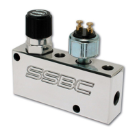
Fasten the prop block assembly using appropriate 5/16" hardware.

Connecting Brake Lines

Line Connection Specifications

All block connections use 3/8"-24 SAE flare for 3/16" brake lines.

Front Brake Master Cylinder Connection

Connect the master cylinder front outlet to the 'F I' port on the Prop Block.

Front Brake Line Connections

Connect the 'F O' ports to the vehicle's front brake lines.

Rear Brake Master Cylinder Connection

Connect the master cylinder rear outlet to the 'R I' port on the Prop Block.

Rear Brake Line Connection

Connect the 'R O' port to the rear brake line, using adapter if needed.

Tighten and Check Fittings

Tighten all fittings with a tube wrench and check for leaks after bleeding.

Switch Connections for Brake Lights

Brake Light Activation Switch

Pressure switch activates brake lights; not used if vehicle has a pedal switch.

Connect Power Supply Wire

Connect the orange wire to a fused constant 12V power supply (15-amp recommended).

Connect Brake Light Output Wire

White wire powers brake light pig tails; connect to turn signal switch if circuit is shared.

Brake System Bleeding Procedure

System Bleeding Requirement

Bleed the brake system after the Prop Block installation is complete.

Master Cylinder Bench Bleeding

Bench bleed the master cylinder if it is new or has run dry.

Gravity Bleeding Process

Gravity bleed each wheel, starting farthest from the master cylinder.

Check Pedal Feel and Leaks

Achieve a firm pedal feel and check all fittings for leaks.

Proportioning Valve Adjustment

Purpose of Valve Adjustment

Balance rear brake pressure with front brakes to prevent rear lock-up during hard braking.

Initial Valve Setting

Start with the valve in the full increase position by turning the knob clockwise.

Adjustment Testing Procedure

Perform hard stops from 30 MPH, adjusting counter-clockwise to decrease rear pressure.

Final Adjustment Verification

Test adjustments at 50 MPH and make further refinements as needed.