10-6 Application Notes
690+ Series AC Drive
Diameter
Calc.
Winder
Speed
Calc
Calculated
diameter
Line
Reference
Line
Speed
Ramp
Calculated reel speed
reference before PID
trim
Web must NEVER slip on
these line reference rolls
Reel speed
Reel Drive must
NEVER slip
default
alternative
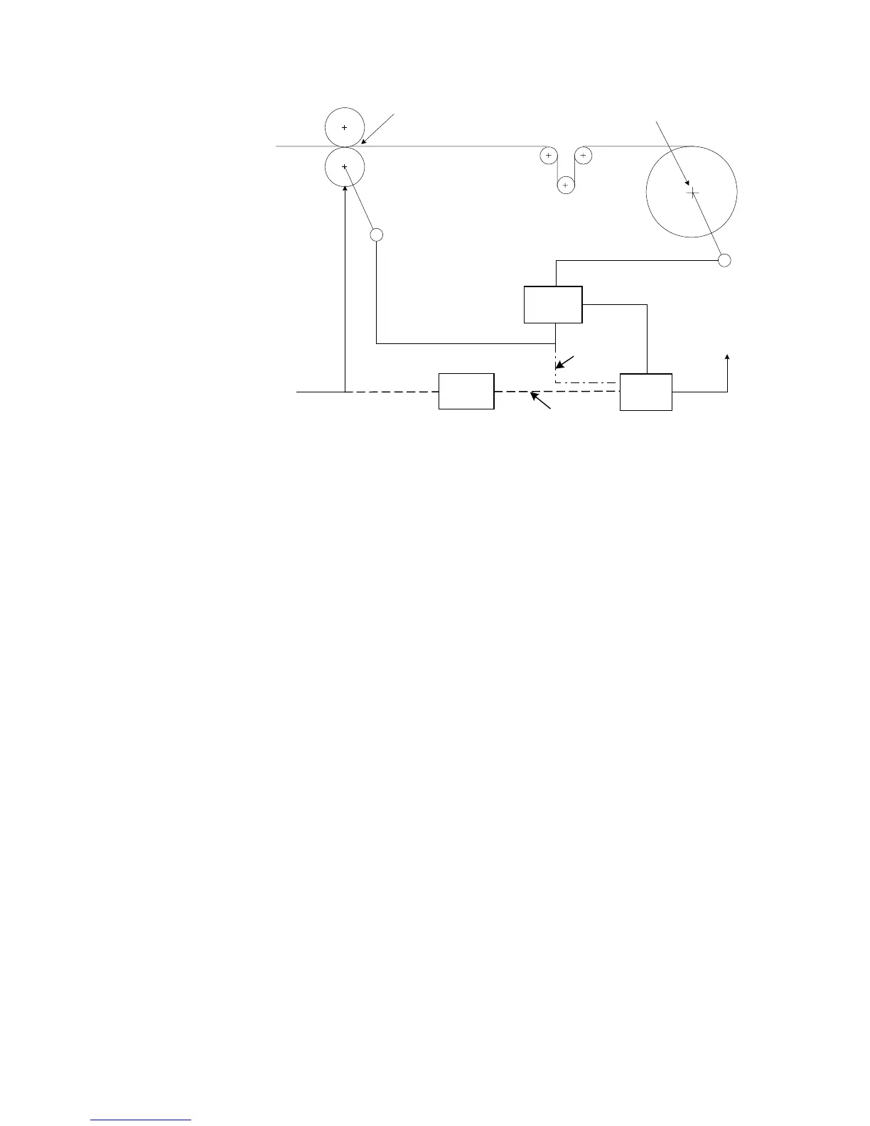
Figure 10-4 Line Reference and Line Speed
By default, Line Speed is connected to ANIN 1 and is used both as Line Reference and Line
Speed.
Alternatively, a separate analog input for Line Reference may be used for the winder speed
calculation.
If an analog tach is used for Line Speed, it must be scaled ±10V full scale.
Note: It is most important for centre wind systems that the web does not slip on the line
reference rolls. Also the reel drive must never slip.
If slipping does occur, the diameter calculator will not be accurate, and very poor winder
performance will result.
Basic Set-up Instruction
This section describes the operations required to set up drives containing the closed loop winder
blocks.
Two different types of closed loop winders are described above, but the basic steps required to
set up the drive are very similar in both cases.
If the drive is configured using the display and keys, it is important to ensure that the parameters
of the drive are saved to the application on a regular basis. If this is not done, parameters
adjusted during the following set-up may be lost if the auxiliary supply to the drive fails.
Information Required
The following information is required from the winding machine manufacturer in order to set up
the winder blocks:
x Absolute minimum roll diameter.
x Absolute maximum roll diameter.
x Absolute maximum line speed.
x Motor maximum speed, at smallest roll diameter and maximum line speed.
 Loading...