4
Application
Access door loudspeaker controller
with line rectier in switch panel
housing as an interface for the con-
nection and power supply of door
components to the Access network.
Application
The combination of ATLC670-…
with ANG600-… can only be used
in connection with Siedle Access.
The devices are used for connection
and power supply to the door sta-
tion and/or the assigned camera.
Any other application is deemed not
in accordance with its intended use
and exonerates the manufacturer
from any liability.
Danger
Mounting, installation and servicing
work on electrical devices may only
be performed by a suitably qualied
electrician.
Failure to observe this regulation
could result in the risk of serious
damage to health or fatal injury due
to electric shocks.
• In a building installation, an all-
pole mains switch with a contact
opening of at least 3 mm must be
provided. The device must not be
exposed to water drops or sprayed
water! Ensure sufcient ventilation,
paying particular attention that ven-
tilation slits are not covered.
• For surface mounting, ensure that
“protection against direct contact”
with active parts is provided. For
details, consult VDE 0100/DIN 57100
part 410.
• When using stranded core as cable
material, this must be tted with
wire end ferrules without fail.
• With a 120V supply, the line recti-
er may only be operated in a closed
switch cabinet. Covering solely with
the ZAP6-0 is not sufcient. With a
120V supply, the line rectier may
only be used in conjunction with ITE
devices. (Information Technology
Equipment)
English
Scope of supply
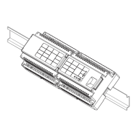
ATLC/NG670-… comprises:
• ATLC670-… Access door loud-
speaker controller for top hat rail
mounting
• ANG600-… Access line rectier
for top hat rail mounting
• This product information
Mounting
The two devices ATLC670-… and
ANG600-… are connected using
the provided ribbon cable prior to
mounting.
Mounting in distribution cabinet
1 Clip the two devices onto the top
hat rail.
Surface mounting
(only in 230V mains)
2 Mounting is only admissible using
accessory ZAP6-0. Engage the
provided catches on the back of the
device ATLC/NG670-… Mount the
devices on the wall.
With different mains voltages,
mounting in suitable distribution
boxes is admissible.
Installation and commissioning
The Access commissioning instruc-
tions and the Access planning and
system manual can be found in the
download area.
Terminal assignment
ATLC670-…
S1
S2
S3
S4
power supply and audio
transmission
D1
D2
data transmission with
digital call and Vario bus
data transmission
V1
V2
Video signal
(two-wire FBAS)
15
16
input via potential-free
contact
E or
17
18
input galvanically isolated
4-30 V DC, 10 mA
13
14 A2
switching contact
30 V AC/DC, 2 A e.g. for
light contact
23
24
A1
output (door release)
AC/DC programmable
10-16 V AC max. 700 mA,
13 V DC max. 300 mA
ANG600-…
L
N
PE
100–240 V AC,
+/–10 %, 50/60 Hz
not assigned
+
-
Output voltage
48 V DC 800 mA
11
12
14
A3
changeover contact
250 V 6 A, circuit breaker
with max.10 A
Specication of the changeover
contact
• Contact load at least
5 V, 100 mA
10 V, 10 mA
24 V, 1 mA
• Admissible switching outputs:
Motor max. 3 A
bulbs max. 1300 W
Energy saving lamps max.
18 x Silvania 7 W or
12 x Osram 11 W
Fluorescent lamps uncompensated
cos j 0.5 max. 800 VA Duo uores-
cent lamps max. 1200 VA
Parallel compensated uorescent
lamps max. 400 VA
Iron core transformers for low-
voltage halogen lamps max. 1000 W
Electronic transformers for low-
voltage halogen lamps max. 1300 W
 Loading...