SECTION ONE – Heater Design and Function
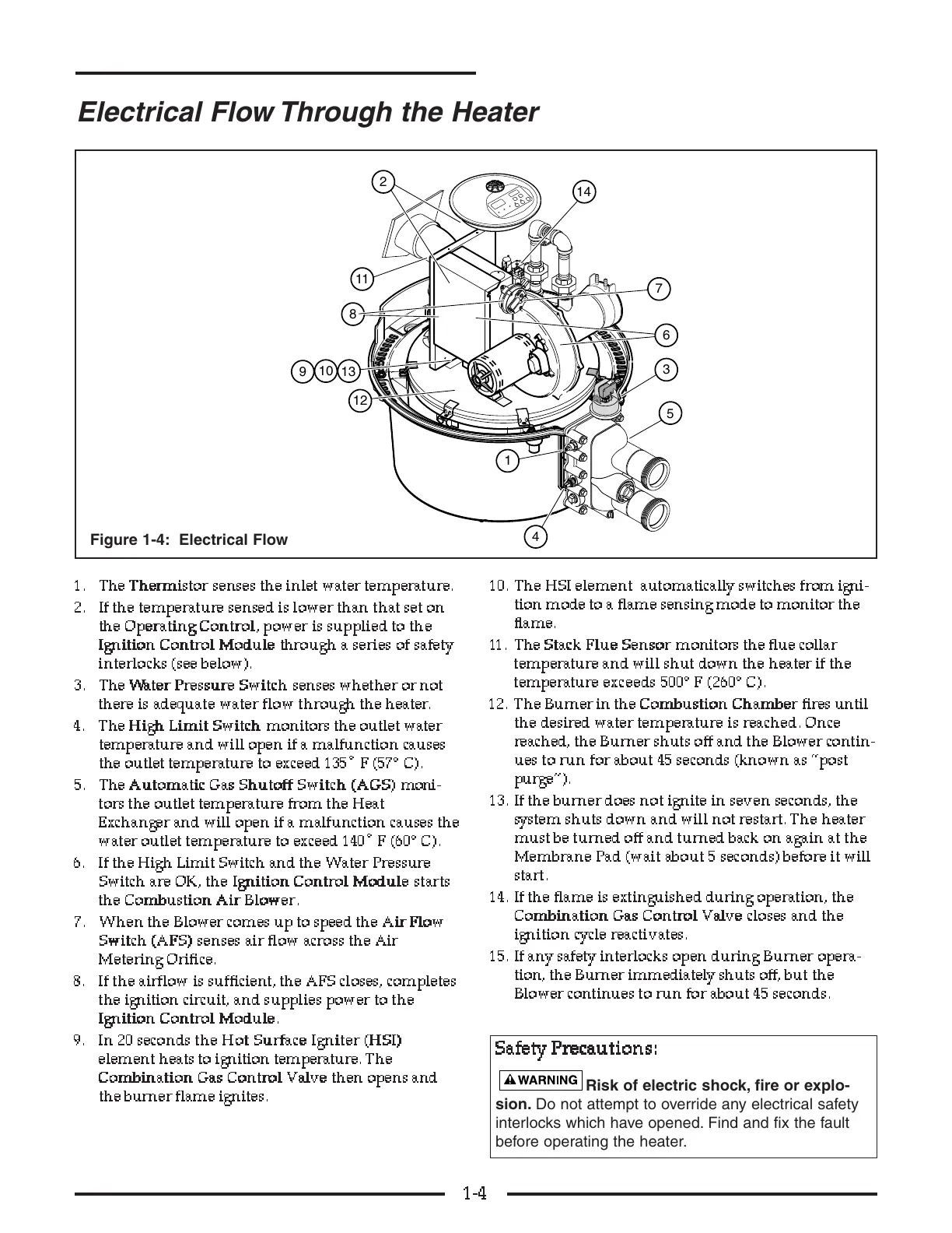
1. The TT
TT
hh
hh
ee
ee
rr
rr
mm
mm
ii
ii
ss
ss
tt
tt
oo
oo
rr
rr
senses the inlet water temperature.
2. If the temperature sensed is lower than that set on
the OO
OO
pp
pp
ee
ee
rr
rr
aa
aa
tt
tt
ii
ii
nn
nn
gg
gg
CC
CC
oo
oo
nn
nn
tt
tt
rr
rr
oo
oo
ll
ll
, power is supplied to the
II
II
gg
gg
nn
nn
ii
ii
tt
tt
ii
ii
oo
oo
nn
nn
CC
CC
oo
oo
nn
nn
tt
tt
rr
rr
oo
oo
ll
ll
MM
MM
oo
oo
dd
dd
uu
uu
ll
ll
ee
ee
through a series of safety
interlocks (see below).
3. The WW
WW
aa
aa
tt
tt
ee
ee
rr
rr
PP
PP
rr
rr
ee
ee
ss
ss
ss
ss
uu
uu
rr
rr
ee
ee
SS
SS
ww
ww
ii
ii
tt
tt
cc
cc
hh
hh
senses whether or not
ther e is adequate water flow through the heater.
4. The HH
HH
ii
ii
gg
gg
hh
hh
LL
LL
ii
ii
mm
mm
ii
ii
tt
tt
SS
SS
ww
ww
ii
ii
tt
tt
cc
cc
hh
hh
monitors the outlet water
temperature and will open if a malfunction causes
the outlet temperature to exceed 135˚ F (57° C).
5. The AA
AA
uu
uu
tt
tt
oo
oo
mm
mm
aa
aa
tt
tt
ii
ii
cc
cc
GG
GG
aa
aa
ss
ss
SS
SS
hh
hh
uu
uu
tt
tt
oo
oo
ff
ff
ff
ff
SS
SS
ww
ww
ii
ii
tt
tt
cc
cc
hh
hh
((
((
AA
AA
GG
GG
SS
SS
))
))
moni-
tors the outlet temperature from the Heat
Exchanger and will open if a malfunction causes the
water outlet temperature to exceed 140˚ F (60° C).
6. If the High Limit Switch and the Water Pressure
Switch are OK, the II
II
gg
g
g
nn
nn
ii
ii
tt
tt
ii
ii
oo
oo
nn
nn
CC
CC
oo
oo
nn
nn
tt
tt
rr
rr
oo
oo
ll
ll
MM
MM
oo
oo
dd
dd
uu
uu
ll
ll
ee
ee
starts
the CC
CC
oo
oo
mm
mm
bb
bb
uu
uu
ss
ss
tt
tt
ii
ii
oo
oo
nn
nn
AA
AA
ii
ii
rr
rr
BB
BB
ll
ll
oo
oo
ww
ww
ee
ee
rr
rr
.
7. When the Blower comes up to speed the AA
AA
ii
ii
rr
rr
FF
FF
ll
ll
oo
oo
ww
ww
SS
SS
ww
ww
ii
ii
tt
tt
cc
cc
hh
hh
((
((
AA
AA
FF
FF
SS
SS
))
))
senses air flow across the Air
Metering Orifice.
8. If the airflow is sufficient, the AFS closes, completes
the ignition circuit, and supplies power to the
II
II
gg
gg
nn
nn
ii
ii
tt
tt
ii
ii
oo
oo
nn
nn
CC
CC
oo
oo
nn
nn
tt
tt
rr
rr
oo
oo
ll
ll
MM
MM
oo
oo
dd
dd
uu
uu
ll
ll
ee
ee
.
9. In 20 seconds the HH
HH
oo
oo
tt
tt
SS
SS
uu
uu
rr
rr
ff
ff
aa
aa
cc
cc
ee
ee
II
II
gg
gg
nn
nn
ii
i
i
tt
tt
ee
ee
rr
rr
((
((
HH
HH
SS
SS
II
II
))
))
element heats to ignition temperature. The
CC
CC
oo
oo
mm
mm
bb
bb
ii
ii
nn
nn
aa
aa
tt
tt
ii
ii
oo
oo
nn
nn
GG
GG
aa
aa
ss
ss
CC
CC
oo
oo
nn
nn
tt
tt
rr
rr
oo
oo
ll
ll
VV
VV
aa
aa
ll
ll
vv
vv
ee
ee
then opens and
the burner flame ignites.
10. The HSI element automatically switches from igni-
tion mode to a flame sensing mode to monitor the
flame.
11. The SS
SS
tt
tt
aa
aa
cc
cc
kk
kk
FF
FF
ll
ll
uu
uu
ee
ee
SS
SS
e
e
ee
nn
nn
ss
ss
oo
oo
rr
rr
monitors the flue collar
temperature and will shut down the heater if the
temperature exceeds 500° F (260° C ) .
12. The Burner in the CC
CC
oo
oo
mm
mm
bb
bb
uu
uu
ss
ss
tt
tt
ii
ii
oo
oo
nn
nn
CC
CC
hh
hh
aa
aa
mm
mm
bb
bb
ee
ee
rr
rr
fires until
the desired water temperature is reached. Once
reached, the Burner shuts off and the Blower contin-
ues to run for about 45 seconds (known as “post
purge”).
13. If the burner does not ignite in seven seconds, the
system shuts down and will not restart. The heater
must be turned off and turned back on again at the
Membrane Pad (wait about 5 seconds) before it will
start.
14. If the flame is extinguished during operation, the
CC
CC
oo
oo
mm
mm
bb
bb
ii
ii
nn
nn
aa
aa
tt
tt
ii
ii
oo
oo
nn
nn
GG
GG
aa
aa
ss
ss
CC
CC
oo
oo
nn
nn
tt
tt
rr
rr
oo
oo
ll
ll
VV
VV
aa
aa
ll
ll
vv
vv
ee
ee
closes and the
ignition cycle reactivates.
15. If any safety interlocks open during Burner opera-
tion, the Burner immediately shuts off, but the
Blower continues to run for about 45 seconds.
1-4
Electrical Flow Through the Heater
Figure 1-4: Electrical Flow
SS
SS
aa
aa
ff
ff
ee
ee
tt
tt
yy
yy
PP
PP
rr
rr
ee
ee
cc
cc
aa
aa
uu
uu
tt
tt
ii
ii
oo
oo
nn
nn
ss
ss
::
::
Risk of electric shock, fire or explo-
sion. Do not attempt to override any electrical safety
interlocks which have opened. Find and fix the fault
before operating the heater.