Do you have a question about the STA-RITE Stack Flue and is the answer not in the manual?
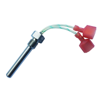
Identifies the position of the Indoor Stack Flue Switch (ES2) / Stack Flue Sensor (SFS) on the Exhaust Elbow.
Explains that the Stack Flue Sensor prevents flue gas output from exceeding 500°F ±18°F (260°C ±8°C).
Details the steps for replacing the Indoor Stack Flue Switch or Stack Flue Sensor, including safety precautions.
Instructions for setting the Control Board to 'SF1' for operation with a Stack Flue Sensor.
Warning regarding burn hazard; advises allowing the heater to cool before touching components.
This document describes the Stack Flue Sensor (SFS), a critical component in heater systems designed to ensure safe and efficient operation. The SFS is an integral part of the heater's safety and control system, specifically designed to monitor and regulate the temperature of the flue gas output.
The primary function of the Stack Flue Sensor is to prevent the flue gas output from exceeding a safe temperature threshold. It acts as a safety device, ensuring that the exhaust gases do not reach temperatures that could pose a risk of fire, explosion, or damage to the heater and its surroundings. Specifically, the SFS prevents the flue gas output from exceeding 500°F ±18°F (260°C ±8°C). This precise temperature control is crucial for maintaining the integrity of the exhaust system and preventing potential hazards associated with overheating.
In older heater models, a similar function was performed by an Indoor Stack Flue Switch or an Outdoor Stack Flue Switch. The SFS is the newer, more advanced component, designed to work with modern control boards for enhanced accuracy and reliability. The control board must be correctly configured to "SF1" for the heater to operate with a Stack Flue Sensor. If the control board is set to "SF0," it indicates compatibility with the older Stack Flue Switches.
The Stack Flue Sensor is designed for seamless integration into the heater's control system. When installed, it continuously monitors the flue gas temperature and communicates this data to the heater's control board. If the temperature exceeds the specified limit, the control board will take appropriate action, such as shutting down the heater, to prevent overheating.
For proper operation, the heater's control board must be correctly configured. If a Stack Flue Sensor is installed, the control board needs to be set to "SF1." The document provides a detailed procedure for setting the control board:
This configuration process ensures that the control board correctly interprets the signals from the SFS and operates the heater safely.
The document provides clear instructions for replacing the Stack Flue Sensor, emphasizing safety precautions throughout the process.
A critical warning is highlighted regarding the installation of the new Stack Flue Sensor: "Risk of carbon monoxide poisoning. BE SURE to seal the Stack Flue Sensor with a bead of RTV sealant before threading it into the exhaust elbow." This step is essential to prevent flue gas leaks, which could lead to carbon monoxide poisoning, a serious health hazard. The RTV sealant ensures an airtight seal, maintaining the integrity of the exhaust system.
In summary, the Stack Flue Sensor is a vital safety and control component in modern heaters, designed to prevent overheating of flue gases. Its precise temperature monitoring, specific installation requirements, and detailed servicing procedures underscore its importance in ensuring the safe and efficient operation of the heating system. Adherence to the provided instructions and safety warnings is paramount for both the longevity of the device and the safety of the user.
| Brand | STA-RITE |
|---|---|
| Model | Stack Flue |
| Category | Accessories |
| Language | English |