SKIMMER LAYOUT and SUCTION LINE SIZING
NOTE: In any installation, there should be at least two main
drains at least three feet apart in addition to any skimmers
installed. A pool may use more than two, but should never have
less
than two main drains.
NOTICE: Installation must comply with all applicable codes,
including NSF Standard 50 (if required). Equalizer lines may be
required on public pool or commercial pool installations.
1. Use one skimmer per 500 square feet of pool surface area.
Suction line sizes are based on a water velocity of less than
seven feet per second. Since building codes vary, check your
local building code before installing pool and skimmers.
2. Suction line sizes for each section of piping must allow for
the total number of skimmers feeding that section of the line.
Suction line sizing in Chart I allows for this.
3. See Figures 5 and 7, Pages 2 and 3, for piping layout. See
Chart I, Page 3, for suction pipe sizing.
4. For good hydraulic balance, divide skimmers as equally as
possible between the main branches of the piping layout.
5. For long pipe runs (in which friction can reduce flow and
pressure), refer to your friction/flow chart for proper pipe
sizes.
6. When planning location of skimmers on one- and two-skim-
mer outdoor pools, locate skimmers so that the prevailing
wind blows into the skimmers.
INSTALLATION
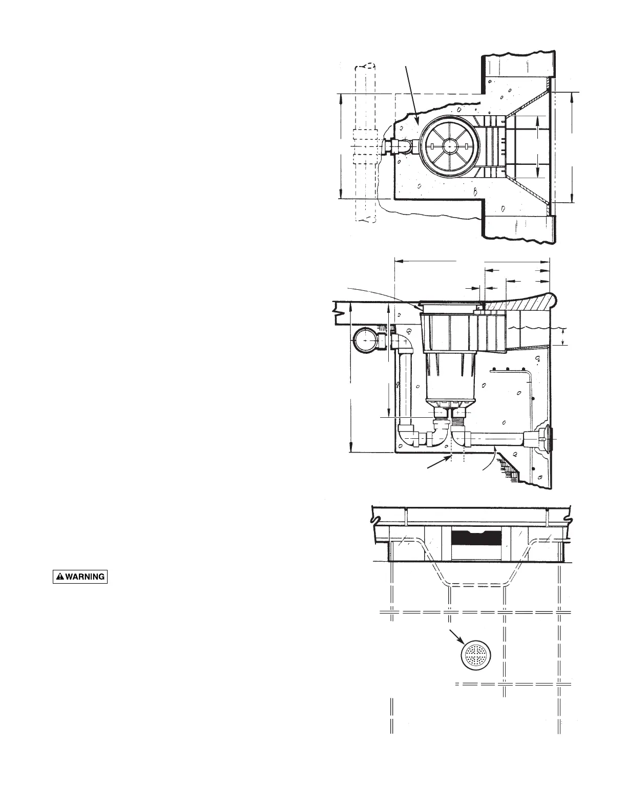
Concrete: See Figure 7 for basic dimensions. Top cover frame
has 1" vertical height adjustment.
NOTICE: Skimmer MUST be surrounded by at least 4" of struc-
tural concrete in a monolithic pour, using a cold joint as shown
in installation drawings.
Line Connections and Testing: Connect pump inlet line to rear
port in bottom manifold (Figure 7). Skimmer is ABS plastic; man-
ifold connections are 1-1/2 or 2" threaded or 1-1/2" slip. For
threaded connections, do not use pipe dope; to seal joint use
RTV Silastic #732* (preferred), teflon tape, or Plasto-Joint Stik**.
For slip connections, apply PVC primer to PVC pipe only. Then
apply ABS to PVC solvent cement to both pipe and slip connec-
tions. Consult dealer for correct solvent cement for pipe used.
Assemble joint per cement manufacturer’s instructions. Allow at
least 3 hours before pressure testing.
Plastic cements and primers can be flammable,
poisonous, or both. Closely follow cement manufacturer’s
instructions when using plastic cement.
In residential installations where equalizers are not required
and where the main drain lines do not connect to the skimmer
equalizer port, low water levels in the pool, spa, or hot tub or
clogged skimmer baskets may damage the pump due to loss of
prime (if skimmer sucks air) or cavitation (if skimmer clogs). Air
pulled in by skimmer(s) can be trapped in filter tanks, which
may be a safety hazard. If skimmer regularly vortexes or sucks
air, raise water level or contact your pool service representative
for advice.
* Dow Corning
** Lake Chemical Co., Chicago, IL
18"
18"
Ref.
10"
Concrete
Plan View
27"
11
1
/
4
Ref.
7
1
/
2
1
"
Vertical
adjustment
of frame to
accommodate
misalignment.
To Pump
Suction
26"
19"
Min.
2" Min.
W.L.
W.L.
1"
2"
2"
Equalizer
Alternate
Line from
Main Drains.
Front View
Figure 8: U-3 Skimmer Installation
Drawings and Specifications
Section View
Use 8011-Series anti-entrapping
55 GPM equalizer fitting with
8010 Series Cover or use 8012
Series Cover on 8429 Wall
Fitting.
Cover must fit tight to fitting to
prevent entrapment.
 Loading...