14
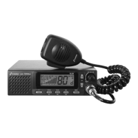
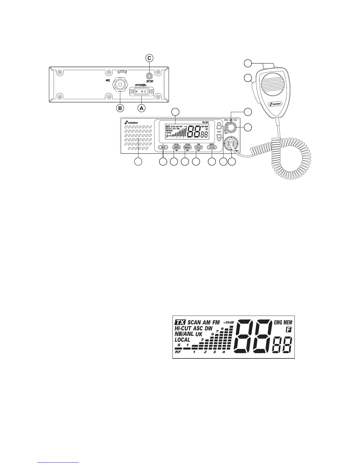
Control elements and connections
1 LC display
2 Volume control (VOL) and ON/OFF switch
3 Squelch (SQ) and A(utomatic) S(quelch) C(ontrol)
4 Front loudspeaker
5 Memory mode MEM, Function key F
6
Type of modulation AM/FM, RF attenuator LOCAL, memory location M1
7 Noise blanker NB/ANL (Automatic Noise Limiter), scan function SCAN, memory location M2
8 Hi-Cut filter HI-CUT, dual watch DW, memory location M3
9 Direct access to channel 19/9 CH19/9, key beep BEEP
10 Keys for channel selection (CH) switching upwards s and downwards t
11 6-pin microphone socket (Mic)
12 Push-to-talk (PTT)
A DC connection 12/24 volts
B Antenna socket, 50 ohms
C Connection for external loudspeaker, 3 watts, 4 - 8 ohms
Displayed for
TX
transmission
SCAN scan
AM modulation type
FM modulation type
HI-CUT activated low-pass filter
ASC activated automatic squelch
DW activated dual watch function
NB/ANL activated noise limiter
UK channel configuration MPT 1382
LOCAL
activated RF attenuator
EMG direct access to channel 19/9
MEM operation in memory mode
F changing the channel configuration
4 5 6 7 8 9 10 11
3
10
12
21
LC display
Channel Channel
configuration
(EU, PL, d, EC, U, In)
xm 5006e
 Loading...