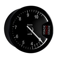
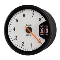
Stack Clubman Tachometer
(Model ST200)
Important Note
Your Tachometer is delivered in demonstration mode.
If you have not set the cylinders the tachometer will
automatically start running when you connect the Power.
Mounting
Fits 80mm (3.25”) cut out. Insert in hole, fit U
bracket and tighten down Nyloc nuts.
Note this Tachometer does not require
any protection against vibration.
Connections
Red
wire to a switched 12V supply.
e.g. Ignition switch (Kill Switch on competition
vehicles).
Orange
wire to the appropriate tachometer signal
pickup point.
Refer to table on following page
Blue
wire to one terminal of the switch, and
the other side of the switch to a convenient
ground point (Black).
Red
Part No. 542046-001
Blue
Orange
Black
Ignition/Kill Switch
Black
wire to the battery negative or
to the same ground connection as the
ignition system.
80mm
(3.25”)
Negative (black) wire of the shift-light to the Tachometer
Blue switch wire and Positive (red) wire of the shift-light to
a switched 12 Volt supply - e.g. Master switch, Ignition
switch.
W
W
W
W
W
ar
ar
ar
ar
ar
ning:
ning:
ning:
ning:
ning: If a non STACK shift light is used the
maximum
maximum
maximum
maximum
maximum
permitted current draw is
0.2 Amps
0.2 Amps
0.2 Amps
0.2 Amps
0.2 Amps. Exceeding this will
per
per
per
per
per
manently damage the T
manently damage the T
manently damage the T
manently damage the T
manently damage the T
acho
acho
acho
acho
acho
.
Stack Shift Light connection (optional)
Setting Engine cylinders
(IMPORTANT please read)
The tachometer is factory set in demonstration mode
.
.
.
.
. If you power up the Tachometer
without setting the cylinders the pointer will automatically start moving.
Set the cylinders as follows:
1. Press & hold the switch
.
.
.
.
.
and apply power to the tachometer.
2. Release the switch when the pointer has stopped resetting on the stop pin.
3. Press the switch immediately
.
.
.
.
.
to select the number of cylinders - the pointer will
move to show the number of cylinders selected.
e.g. Press 4 times for 4 cylinders (pointer will point to 4000 RPM)
4. When the desired number of cylinders have been selected wait
j
j
j
j
j
3 seconds and
the tachometer will resume normal operation with the new setting.
5. To check the setting repeat operations 1 & 2 above, the pointer will move to the
selected number of cylinders. After 3 seconds the unit will revert to normal mode.
.
.
.
.
.
X
Note: For 2 stroke ignition systems set the cylinders to double the actual number of cylinders.
For multi-coil ignition systems use the tach output provided or connect to one coil only and
configure the tacho for the cylinders the coil fires.
When using a dedicated Tacho output check the number of pulses per engine
revolution :- 1 pulse per rev = 2 cylinders (4 stroke) = 1 cylinder (2 stroke)
Ignition system Connection point (Orange wire)
Coil Negative (Low tension)Coil & Points
HEI systems
Magneto (Ext. or Int)
MSD
Coil Negative (Low tension)
Ground switch terminal (magneto side)
Tachometer output
Magneto CD (2 stroke) Use HT pick up (ST697)
Ignition connection table
Red
Black
12V
Blue wire
from Tachometer
2W Max