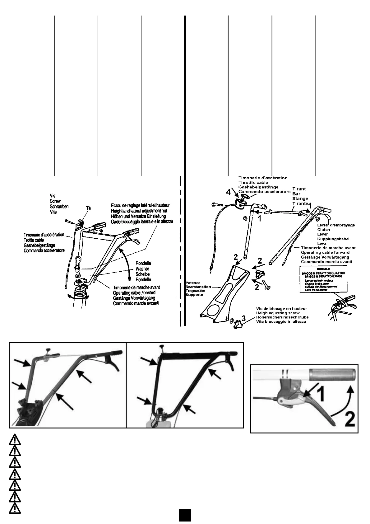
MONTAGE DU
MANCHERON
1) Assembler le guidon.
2) Visser l’écrou de blo-
cage. Le mancheron est
bloqué latéralement et
en hauteur.
3) Dérouler la timonerie
d’accélérateur et blo-
quer la commande à
l’aide du boulon M6x45
sur le côté droit du
mancheron.
NOTE : La commande
d’accélération est réglée
en usine
4) Accrocher les colliers de
gaine.
HANDLEBAR
ASSEMBLY
1) Assemble the handlebar.
2) Screw down and tighten
the latéral and height
adjustment with nut.
The handlebar is now in
the locked position.
3) Unwind the throttle
cable and fit the throttle
lever to the right land
handlebar with the hex.
bolt M6x45mm.
NOTE : The throttle
control is pre-set at the-
factory.
4) Fit the cable-clips to the
handlebars.
AUFBAU
DES STERZES
1) Bewegen sie des sterzes
solange auf.
2) Die Sicheurungsmutter
festchrauben des Sterz ist
nun seitlich und in Höhe
blockiert.
3) Das Gashebelgestânge
abrollen und die
Steuenung mit der
Durchsteckschraube
M6x45 rechts am
Sterz blockieren.
BEMERKUHG : Der
Gashebel würde im Werk
eingestellt.
4) Die KIemmschellen befes-
tigen.
MONTAGGIO
DEL MANICO
1) Alzare il manico.
2) Avitare il dado di bloc-
caggio. Il manico e’bloc-
cat lateralmente e all
altezza.
3) Volgere il filo dell accele-
ratore e bloccare il com-
mando con l’aiuto di un
bullone M6x45 sul lato
dx del manico.
NOTA: II commando dell’
acceleratore e’ regolato
in azienda.
MONTAGE DU
MANCHERON
-1 Emboîter le tirant sur les
bras du guidon et visser
les écrous.
-2 Mettre en place les bras
de guidon sur la potence
et assembler à l’aide des
2 boulons M8x 45.
-3 Régler la hauteur des
guidons avec la vis.
-4 Dérouler la timonerie
d’accélérateur et bloquer
la commande à l’aide du
boulon M5 x 40 (la com-
mande d’accélération est
réglée en usine).
-5 Accrocher la timonerie
d’embrayage sur le
levier.
- 6 Accrocher les colliers
de gaine.
HANDLEBAR
ASSEMBLY
- 1 Fit the bar on the han-
dlebar and fix the screws.
-2 Fit the handlebar on
the rear stanchion and
fix with the two screws
M8x45.
-3 Adjust handlebar height
by acting on screw.
-4 Unwind the throttle cable
and fix the thrott-le lever
with the bolt M5 x 40 (the
throttle control is pre-set
at the factory).
-5 Fit the clutch controls to
the bracket.
-6 Fit the cable-clips to the
handlebar.
AUFBAU
DES STERZES
-1 Den stange an der
Tragsaüle eingeben und
Schrauben blockiert.
-2 Den sterz mit der
Tragsaüle durch die
Schrauben befestigen.
-3 Die richtige Arbeitshöhe
der Sterz einstellen.
-4 Das Gashebelgestänge
abrollen und die Sleue-
rung mit der Durchs-
teckschraube M5 x 40
(der Gashebel würde im
Werk eingestellt).
-5 Die Kupplungsgestänge
am Griff befestigen.
- 6 Die Klemmschellen
befestigen.
MONTAGGIO
DEL MANICO
-1 lnfilare il tirante sul le
stegole e avvitare il dado.
-2 Montare le stegole sul
supporto e fissare con
2 bullone M8x45.
-3 Regolare l’altezza delle
stegole con vite.
-4 Volgere il filo dell’ acce-
leratore e blocare il com-
mando con bullone M5x
40 (il commando dell’
acceleratore e regolato
in azienda).
-5 Fissare filo dell frizions.
-6 Fissare i fermacavi.
3
Accrocher les colliers de gaine.
Fit the cable-clips to the handlebar
Die Klemmschellen befestigen.
Fissare i fermacavi.
Colocar las abrazaderas de los cables de embrague y accelerator.
Zet kabels en stangen met de medegaleverde kabelbinders vast.
Fixar as braçedeiras.
UTILISATION DE LA COMMANDE
OPERATING METHOD
BEDEINUNG
FUNZIONAMENTO
METODO DE FUNCTIONAMIENTO
BEDIENING VOORSCHRIFTEN
 Loading...