4. Relay board tests.
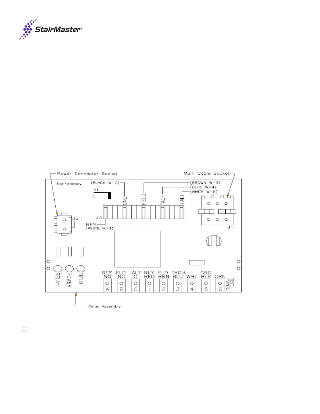
• Disconnect the main cable from relay board J1 terminal.
• With power on, place jumper across GND/BLK and RLY/RED test points.
o Relay LED should light. If not, replace lower PCB board (SM23545).
• With power on, place jumper across +/WHT and FLD/BRN test points.
o Field LED should light. If not, replace lower PCB board (SM23545).
● Disconnect the black W-2 ground wire. With power on now, place a jumper on the +/WHT test point and with the
other end touch the ALT/C test point, then jump the +/WHT to the FLD/NC test point, and then jump the =/WHT to
the RES/NO test point. Once the test is completed, re-attach the black W-2 ground wire and the J-1 main cable
socket which was removed at the beginning of the relay board test .
o Field LED should light. If not, replace lower PCB board (SM23545).
Last revised 10/5/15
 Loading...