This document serves as a comprehensive user manual for the STAMOS Soldering Laboratory Power Supply, covering models S-LS-90, S-LS-91, S-LS-92, S-LS-93, S-LS-94, and S-LS-95. It provides essential information for safe and reliable operation, technical specifications, and maintenance procedures.
Function Description
The STAMOS Soldering Laboratory Power Supply is designed to provide external receivers with direct current (DC) at specified voltage and intensity levels. It acts as a stable power source for various laboratory and electronic applications. The device features both voltage and current stabilization modes, ensuring consistent output parameters regardless of load variations. It also incorporates overload protection to safeguard both the power supply and connected equipment.
Important Technical Specifications
The power supply units operate on a 230/50 V~/Hz supply voltage. Key specifications vary by model:
| Parameter |
S-LS-90 |
S-LS-91 |
S-LS-92 |
S-LS-93 |
S-LS-94 |
S-LS-95 |
| Rated power [W] |
300 |
200 |
300 |
180 |
300 |
150 |
| Voltage regulation range DC [V] |
0-100 |
0-100 |
0-60 |
0-60 |
0-30 |
0-30 |
| Current regulation range [A] |
0-3 |
0-2 |
0-5 |
0-3 |
0-10 |
0-5 |
All models share the following characteristics:
- Operation stabilization coefficient: CV≤0.3%+10 mV, CC≤0.3%+10 mA
- Operation stabilization coefficient under load (FS – full range): CV≤0.5%FS, CC≤0.3%FS
- Ripples: CV≤ 0.3 % mV r.m.s., CC≤ 0.3% mA r.m.s.
- Resolution:
- S-LS-90, S-LS-91: ±0.5%FS ± 1digital
- S-LS-92, S-LS-93, S-LS-94, S-LS-95: ±0.3%FS ± 1digital
- Safeguards: OCP (Over Current Protection), OTP (Over Temperature Protection), OPP (Over Power Protection)
- Ambient temperature during operation: -10÷40 °C / < 80 % relative humidity
- Ambient temperature during storage: -20÷80 °C / < 70 % relative humidity
- IP Code: IP20
- Dimensions (Width x Depth x Height; mm): 220x70x150
- Weight [kg]: 1.2
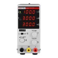
The device features a front panel with a voltage value display (3), current value display (4), and output power value display (5). It includes a switch (6) for output current stabilization mode/overload protection activation, a voltage value regulation knob (7), an On/Off button (8), and a current value regulation knob (9). Output terminals consist of a negative polarity terminal (10), a grounding terminal (11), and a positive polarity terminal (12). The rear panel includes an exhaust fan (14), a switch for input voltage (110/230V) (15), a power supply socket (16), and a fuse socket (17).
Usage Features
Preparation for Work:
The device should be placed in an environment where the ambient temperature does not exceed 40°C and relative humidity is below 85%. Adequate air circulation is crucial, requiring a minimum distance of 10 cm from any wall. It must be operated on a level, stable, clean, fireproof, and dry surface, out of reach of children and individuals with reduced mental, sensory, or intellectual abilities. Ensure the power supply plug is always accessible. For optimal stability, it is recommended to turn on the device 30 minutes before starting work.
Working with the Device:
- Connection: Connect the power supply cable (18) to the socket (16) on the rear panel.
- Power On: Switch on the device by pressing the On/Off button (8).
- Setting Output Parameters:
- Voltage Regulation Mode: Turn the current regulation knob (9) clockwise to maximum. Use the voltage regulation knob (7) to set the desired voltage. Connect the external load to terminals (10) and (12). In this mode, the device provides a constant, set voltage, while the current varies with the load. The C.V indicator (2) should be lit.
- Current Regulation Mode: Set the switch (6) to "CC" position. Turn the current regulation knob (9) clockwise until the CV indicator lights up, then set the voltage to 5-8V using knob (7). Turn the current regulation knob (9) counter-clockwise to minimum. Connect output terminals (10) and (12) with wires. Adjust the current value with knob (9). After setting the current, turn the voltage regulation knob (7) counter-clockwise to minimum, then remove the connecting wires. Connect the load to the output terminals. Turn the voltage regulation knob (7) clockwise until the C.C indicator (1) turns on. In this mode, the current is constant, and the voltage varies with the load.
Overload Protection (OCP):
- Set switch (6) to "CC" position.
- Connect terminals (10) and (12) with wires to regulate the current value, which will be the threshold for protection activation. Remove the wires.
- Set switch (6) to "OCP" position to activate protection.
- Set the desired output voltage with knob (7). Connect the load to terminals (10) and (12). If a short circuit or abnormal behavior occurs, the output current will increase. If the set value is exceeded, the protection cuts power to the outputs and an audible alarm sounds.
- To reset protection, disconnect the load, then set switch (6) to "CC" and back to "OCP". Note that OCP protection prevents operation in current stabilization mode.
Safety Guidelines:
- Always read and understand the manual before use.
- Ensure the power plug matches the socket and avoid modifications.
- Do not touch earthed parts or the device with wet hands.
- Keep the power cable away from heat, oil, sharp edges, or moving parts.
- Use a Residual Current Device (RCD) in wet environments.
- Do not use the device with a damaged power cable.
- Never immerse the device, cable, or plug in water or other liquids.
- Do not operate the device if tired, ill, or under the influence of substances that impair judgment.
- The device is not a toy; children should be supervised.
- Maintain a tidy and well-lit workspace.
- Do not use in explosive atmospheres.
- Report any damage or malfunction immediately.
- Repairs should only be performed by qualified service personnel using original spare parts.
- Do not remove factory-installed covers or loosen screws.
- Do not move, shift, or rotate the device during operation.
- Do not leave the switched-on device unattended.
- Do not cover the ventilation openings.
- Avoid prolonged full-load operation to prevent damage.
- Output voltage should not exceed the input voltage of the powered device.
- Disconnect external load cables before changing operation mode.
- When operating with inductive loads, change voltage/current slowly and never switch power on/off with an inductive load connected.
- Ensure input voltage matches the selector setting to prevent malfunction or damage.
Maintenance Features
Cleaning and Maintenance:
- Always disconnect the power plug before cleaning or when not in use.
- Use only non-corrosive agents for surface cleaning.
- Thoroughly dry all components after cleaning before reuse.
- Store the device in a dry, cool place, protected from moisture and direct sunlight.
- Do not spray the device with water or immerse it.
- Ensure no water enters through the ventilation openings.
- Clean ventilation openings with a brush and compressed air.
- Regularly inspect the device for technical faults and damage.
- For fire protection, replace the fuse only with the specified type and class.
Fuse Replacement:
- A specialist technician should replace the fuse.
- Disconnect the device from the power supply.
- Disconnect the power supply cable and remove the fuse socket.
- Replace the fuse with a new one of the same parameters.
- Reassemble the fuse socket.
- Avoid excessive force when removing or installing the fuse socket to prevent damage.
Disposal of Used Devices:
This product must not be disposed of with normal household waste. It should be taken to a collection point for recycling electrical and electronic devices, as indicated by the symbol on the product, manual, or packaging. Materials used in the device are recyclable. Proper disposal contributes significantly to environmental protection. Information on appropriate disposal points can be obtained from local authorities.