
L
Lauren JenningsAug 3, 2025
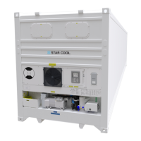
What to do if my Star Cool Refrigerator unit will not start up?
- SSherri WilsonAug 4, 2025
If your Star Cool Refrigerator unit won't start, first ensure it's receiving power. Then, inspect fuses QS1, F1, and F2 to see if any are blown. Also, check the alarm list and clear any active alarms along with their causes. If the unit is wired for emergency operation, make sure the parameter F03 FC type under the service menu is set to NONE, and that the wires have been correctly mounted for emergency operation.