Titan Quick Start Guide - Version 0.46 6
2. Installation & Wiring
Before proceeding with the installation of the reader, it is recommended to have a proper site plan. For
licensed frequency installations, the frequencies to be used are also needed. A site plan will dictate which
cables are needed for your application.
1 Connections
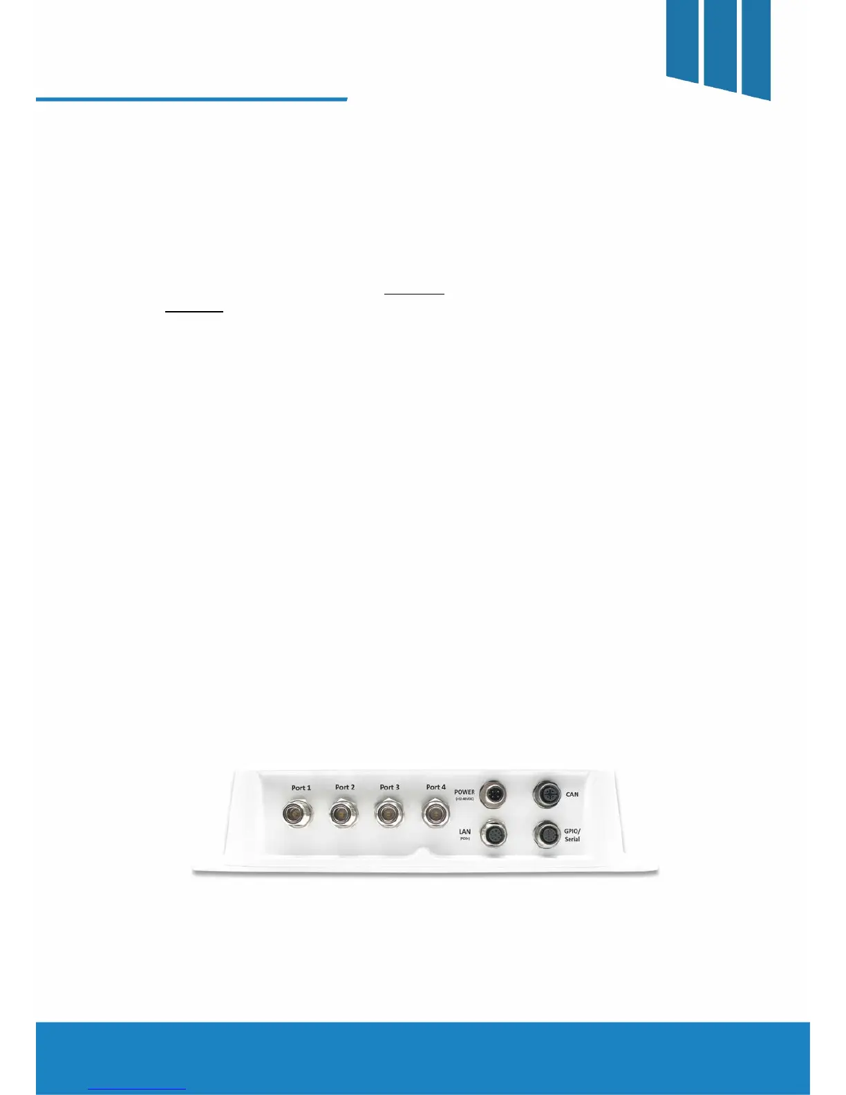
The connector faceplate diagram is shown in FIGURE 1. A schematic of the possible interconnections is
shown in FIGURE 2.
A. DC Power
The Power connector is used in applications where the Power Over Ethernet (POE+) is not being utilized.
The input range for the Power ranges from 12 – 48 VDC at the reader. It is recommended to measure the
actual voltage at the reader to make certain it is within specification.
B. Network (LAN) and PoE+
The LAN connector is used for all the Ethernet connections that are routed to the reader. This includes any
PoE+ connections. Refer to the diagram below for the proper routing of connections.
(* All features of the Titan are supported by either DC power or PoE+. It is also permissible for the User to connect both
DC power and PoE+ to the reader simultaneously.)
C. Controller Area Network (CAN)
The CAN connector may be used where a dense reader population is prevalent when using specific
protocols. Please refer to the User Guide for additional information regarding the CAN functionality.
D. GPIO / Serial
The GPIO/Serial connector is used for serial communications and various I/O. The Titan reader supports up
to 2 optically isolated inputs as well as 2 open collector outputs. Please refer to the User Guide for more
information regarding the serial port and I/O capabilities.
E. RF Ports
The Titan supports up to 4 antennas connections simultaneously with various protocols. Please refer to the
User Guide for specifics.
FIGURE 1 - Connector Faceplate Arrangement
 Loading...