30 А
+ 12 V
3 А
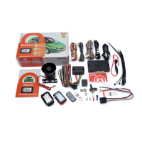
E96 BT, E96, E66 BT, E66
868 MHz antenna
Bluetooth antenna
X1
X2
X2
X3
X4
X5
USB-connector
Autostart connection diagrams for E96
+12 V
Ignition lock
Starter
Ignition 1
Ignition 2
Accessories
+12 V
StarLine BP-03, BP-05
1 А
+12 V
StarLine BP-06
orange-violet
orange-white
blue-red
pink
yellow
gray-black
green-yellow
black-red
yellow-white
black-white
black
red
gray
green
orange-gray
yellow-red
blue-black
yellow-black
blue
X1
violet-yellow
not used
Connection diagram
86
30
85
87
87а
(–)
(+)
Variant 1
Variant 2
10 А
86
30
85
87
87а
86
30
85
87
87а
+12 V
(–)
(+)
(–)
(+)
Activators are
connected in parallel
command
«Close»
command
«Open»
yellow-orange violet
or
Service button with LED
Temperature sensor
For convenient setting, diagnostics and software update use the StarLine Master program,
available for download on the website help.starline.ru/slm
Enter the program using the service code given on the owner’s plastic card.
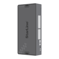
Recommendations for accommodation
The main unit should be installed at a distance of at least 10
cm from the metal surfaces, in order to avoid deterioration of
reception quality of the Bluetooth and 868 MHz antennas
For cars with a САN/LIN-bus make a connection via the digital CAN/LIN-bus, for other cars make
an analogue connection.
Information on connection to the CAN/LIN-bus of different cars is available on website
can.starline.ru
Common
Blocking relay
in the set
NC
NO
Ignition 1
Storage battery
Door opening simulation output (200 mA) (–)
Unit power supply
Security status output (200 mA) (–)
Engine blocking (200 mA) (–)
“Comfort” function output (200 mA) (–)
Engine operation monitoring input
Ignition input (+)
Bypass module control output (200 mA) (–)
Parking brake input (–)
Control output for code relay StarLine R4 (200 mA) (–)
Trunk limit switch input (–)
Horn control output (2 A) (+)
Brake pedal input
Trunk unlocking output (200 mA) (–)
Door input (+/–)
Door two-step unlocking output (200 mA) (–)
Hood limit switch input (–)
General installation specications
The complex is designed for installation on vehicles with a voltage of 12V onboard power supply.
Before the complex installation, make sure that the circuits of the electrical equipment of the vehicle, to which the
complex is connected, are in good working order, and also in the absence of error indication of the vehicle's factory
equipment.
The complex installation should be carried out in accordance with the connection diagram.
First of all, you should connect the "ground" wire of the complex to chassis ground.
Wiring should be made as far as possible from sources of electrical interference: ignition coils, high-voltage wires, etc.
Pay attention to the fact that the wires do not come in contact with the moving parts of the vehicle's construction -
pedals, steering rods, etc.
Power supply to the components of the complex is allowed only after the installation is completed.
Do not install the engine temperature sensor near the exhaust manifold, as this may cause the sensor to overheat
and malfunction.
The complex installation should be carried out only by specially trained qualified installers.
When configuration the complex the parameters to be set must not contradict the requirements of the vehicle
guide.
Connection diagram for StarLine R4 code relay
OUTPUT
IGN
INPUT
EXT
COM
NC
NO
LOCK
BAT
GND
orange-gray
brown
orange
black-yellow
blue
green
black-white
black
red
yellow
gray
UNLOCK
(-)
(+)
86
30
85
87
To connector X1 yellow-orange wire
Hood limit switch
Power
Ignition
Hood lock
External blocking relay
Common
Blocked circuit
Blocked circuit
NC
LIN1
CAN-L B
LIN2
CAN-L A
CAN-H A
StarLine Bus core bus
DVR control output (2А) (+)
CAN-H B
Output to alternative light signal control (200 mA) (–)
Output to alternative central lock control (200 mA) (–)
Output to accessories (200 мА) (–)
Output to starter (200 мА) (–)
Output to ignition 1 (200 мА) (–)
Output to ignition 2 (200 мА) (–)
Output +12В (500 мА) (+)
Control output of the built-in starter lock (200 мА) (–)
To connector
X2
To the yellow
wire of
connector X1
Power module
orange-black
green-black
brown-white
blue-black
brown
white
orange
gray
orange-white
white-black
red
orange
yellow
black-yellow
blue
green
After completing the installation of the complex, be sure to
set the current date and time from the remote (see short
user manual).
or
The developer and manufacturer, StarLine SPA, reserves the right to make technical
improvements not shown in this diagram.
Information on updates, current versions of operation and installation manuals are available on
the website
www.starline.ru in section “Catalogue”. Charts of mounting on different car
models are available on website
install.starline.ru
Other possible connection
options are available on the
website www.starline.ru