Do you have a question about the StarTech.com USB2G4LEXT2NA and is the answer not in the manual?
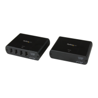
Connect Local Extender RJ45 to a Network Device RJ45 port.
Position the Local Extender near the Host Computer.
Connect Local Extender USB-B to Host Computer USB port.
Press and hold Mode button on Local Extender; Link LED flashes.
Press and hold Mode button on Remote Extender within 10 mins.
Link LEDs flash slowly then turn solid to indicate link.
| Master (outer) case width | 406 mm |
|---|---|
| Master (outer) case height | 270 mm |
| Master (outer) case length | 558 mm |
| Quantity per master (outer) case | 14 pc(s) |
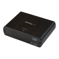
| Type | Console transmitter & receiver |
| Certification | CE, FCC, REACH |
| Plug and Play | Yes |
| Product color | Black |
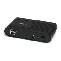
| LED indicators | Activity, Link, Power |
| Housing material | Steel |
| Cable types supported | Cat5e, Cat6, Cat7 |
| Ethernet interface type | Gigabit Ethernet |
| Maximum transfer distance | 100 m |
| Sustainability certificates | RoHS |
| RJ-45 ports quantity | 2 |
| USB 2.0 Type-A ports quantity | 4 |
| USB 2.0 Type-B ports quantity | 1 |
| Input current | 0.6 A |
| Input voltage | 100 - 240 V |
| Output current | 1 A |
| Output voltage | 24 V |
| Power plug type | Type M |
| Power consumption (typical) | 24 W |
| Cables included | AC, USB |
| Storage temperature (T-T) | -10 - 60 °C |
| Operating temperature (T-T) | 0 - 50 °C |
| Operating relative humidity (H-H) | 20 - 80 % |
| Depth | 100 mm |
|---|---|
| Width | 76 mm |
| Height | 26 mm |
| Weight | 192 g |
| Package depth | 245 mm |
| Package width | 195 mm |
| Package height | 78 mm |
| Package weight | 932 g |