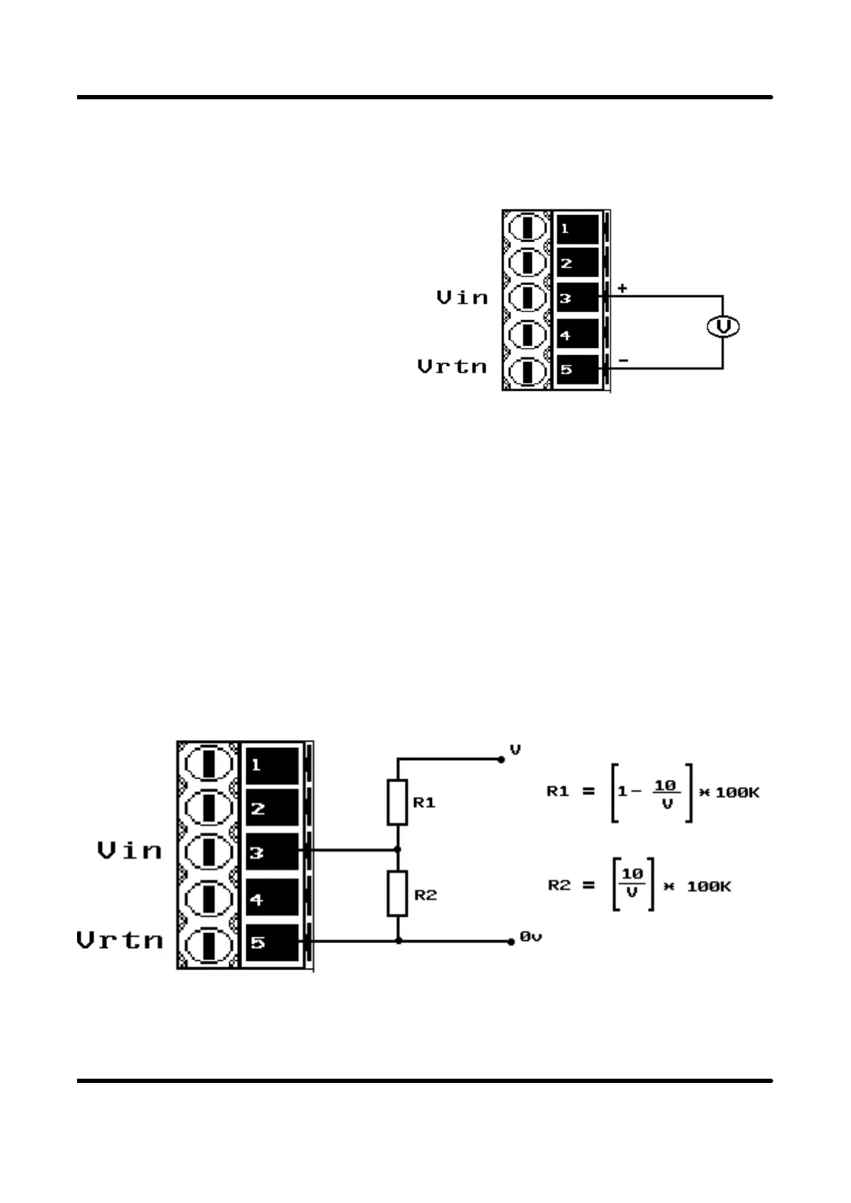
3.2.1.2 VOLTAGE INPUT
This input pin can take voltages up
to 10 volts. The signal should be
connected between pins 3 and 5 as
indicated.
3.2.1.3 VOLTAGES GREATER THAN 10 VOLTS
In order for these to be measured correctly, it is necessary to connect some simple
external circuitry outside the unit to divide down the voltage to a nominal maximum of
10volts. This is done using a resistor divider chain as shown in the diagram below.
The choice of resistors are given as the nearest preferred values to those calculated in
the equations for R1 and R2 below. It is possible to correct for any errors in the
divide down chain by making R2 a trimmer, or correct by adjustment of scale range.
Care must be taken to insulate any high voltages to protect from electric shocks or
damage to any other equipment.
SENSOR CONNECTIONS
Page 13