POWER SUPPLY
3.0 WIRING
This section describes how the instrument should be wired for the Power Supply,
Input Sensor or any Output options that may be fitted. All connections are made to
three or five way sockets which are removable for ease of wiring.
Installation should be undertaken in accordance with relevant sections of
BS6739 - British Standards code of practice for "Instrumentation in Process
Control Systems: Installation design and practice".
See important safety information on page 8
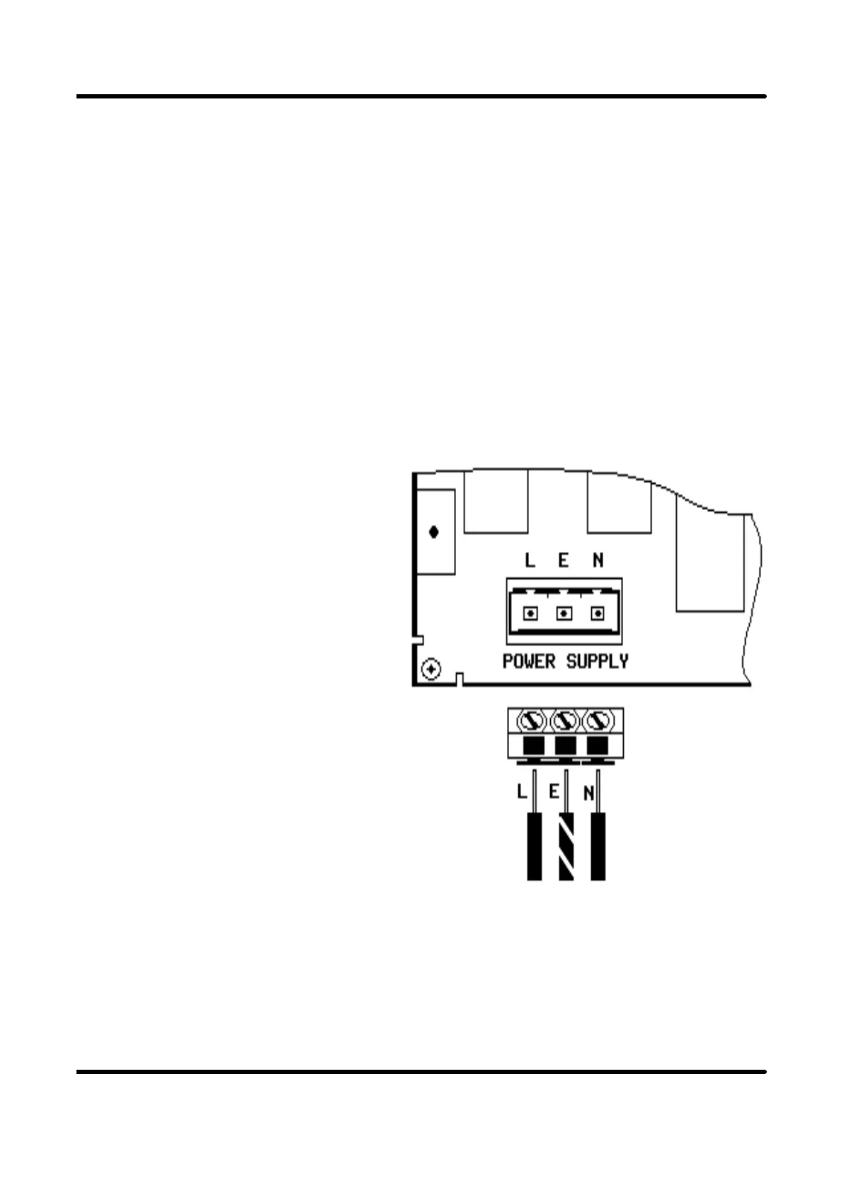
3.1 POWER SUPPLY
The Power supply rating will be
indicated on the top of the instrument.
Ensure that this is correct for the
voltage that is to be connected. If
there is a difference, refer to Service
Manual for details of power supply
adjustment.
Note that the power supply socket has
had polarisation keys fitted to prevent
insertion into any other plug at the rear
of the instrument.
The connection is made as shown.
Ensure that no bare wire protrudes from
the rear of the power connector risking
a short circuit.
Page 10