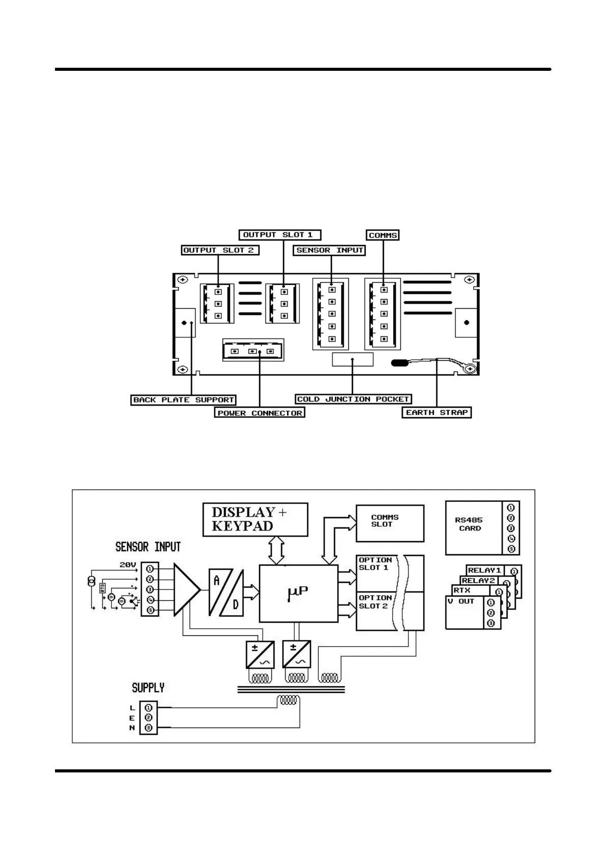
The diagram of the rear panel below shows the slot positions for all electrical
connections.
There are two output slots into which the user may fit a range of options, including
relays, current re-transmission and voltage output boards. In addition there is also a
communications board slot allowing up to 30 units to be directly networked together
to a host computer.
A schematic of the unit showing internal power supplies and possible options is
shown below
Page 5