APPENDIX E
USER COMMUNICATION SOFTWARE
This section aims to provide sufficient information to enable a user to write software
for a Personal Computer to interface directly with instruments on a network. As all
configuration and runtime data are available via the comms, there is great potential to
tailor a system to a users individual requirements.
Information for electrically connecting a network of units is dealt within the wiring
section of this manual. This section explains the software interface and the basic
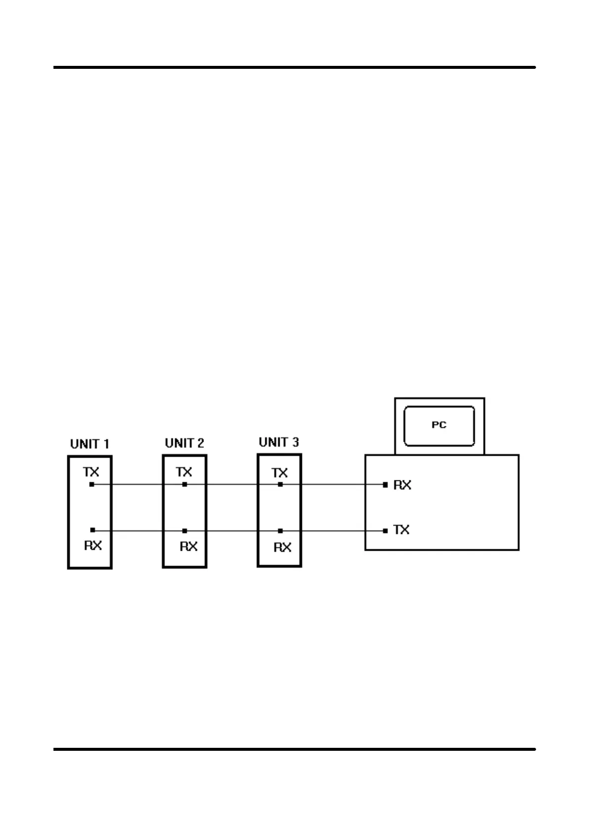
comms operation of the instrument. The schematic of a typical network showing three
instruments is shown below. Note that this is not wiring detail, only a schematic of
signal interconnections.
You will notice that the transmit lines from the units are connected together. This
means that only one unit can transmit at a time without clashing the signal. For this
reason the communication software in the instrument(s) only responds to messages
issued by the PC. No messages are generated spontaneously by the units, in this way
the PC maintains control over the network. Thus the PC is regarded as the MASTER
and the units on the network are SLAVES.
APPENDIX E
Page 83