EasyManua.ls Logo

Steelmate 888W1 User Manual

Steelmate 888W1
16 pages
To Next Page IconTo Next Page
Page #1 background imageLoading...
Page #1 background image

Questions and Answers:

Steelmate 888W1 Specifications

General IconGeneral
BrandSteelmate
Model888W1
CategoryCar Alarm
LanguageEnglish

Summary

Reasons to Choose Steelmate

Important Safety and Usage Notices

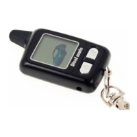
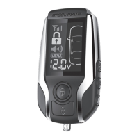
Transmitter Overview

LCD Screen and Indicators

LCD Screen Symbols

Explanation of the symbols and indicators displayed on the LCD transmitter screen.

Transmitter Battery Status

Details on the battery status display and charging requirements for the transmitter.

Transmitter Charging Procedure

Instructions on how to connect and charge the remote transmitter's battery.

System Operation Guide

Status Indication Meanings

LED Indicator Status

Meaning of different LED flashing patterns indicating system status.

Parking Light Status

Interpretation of parking light flashes to understand system status and events.

Siren Chirp Status

Understanding the meaning of various siren chirp patterns for system feedback.

Core System Functions

Arming the System

Steps to arm the car alarm system, including lock confirmation and LED indication.

Passive Arming Mode

Automatic arming feature that engages the system after a set time if doors are closed.

Disarming the System

Procedure to disarm the car alarm system and unlock the doors.

Silent and Mute Arming/Disarming

Operating the system without audible siren chirps.

Car Searching Function

Locating the vehicle using the alarm system's siren and light signals.

Remote Sensor Bypass

Temporarily disabling shock sensors for specific arming scenarios.

Central Door Lock Control

Managing door locking and unlocking based on ignition, speed, or footbrake.

Dome Light Delay Feature

System arming delay synchronized with the vehicle's dome light.

Remote Panic Alarm

Activating the siren and lights for emergency situations.

Time, Alarm, and W-Mode Settings

Adjusting clock, alarm times, and W-mode transmitter signal timing.

Low Battery Warnings

Understanding and responding to low battery alerts for the transmitter.

Trunk Release Operation

Using the transmitter to remotely open the vehicle's trunk.

Arming Without Transmitters

Manual arming procedure using the valet switch when the transmitter is unavailable.

Anti-Hijack Mode Operation

Activating and managing the anti-hijack feature for vehicle security.

Transponder Card Functionality

Using an optional transponder card for system access and engine immobilization.

Valet Service Mode

Engaging the valet mode for service or parking, restricting certain functions.

Emergency Override Procedures

Disarming the system using emergency override if the transmitter is lost or fails.

Turbo Timer Mode

Using the turbo timer to keep the engine running for a set period after ignition off.

Transmitter Range Indication

Understanding the signal icon on the LCD transmitter to gauge operational range.

Automatic Re-arming

System's ability to re-arm automatically if disarmed and doors are not opened.

Ultrasonic Sensor (Optional)

Functionality and alarm triggers related to the optional ultrasonic motion sensor.

Tamper Alert System

Notification via siren and parking lights if the alarm was triggered while away.

Personal Code Setting

Setting and changing the personal code for system access and programming.

Transmitter and Transponder Coding

Procedures for learning new transmitters and programming optional transponder cards.

System Programming Functions

Guide to programming various system features using transmitter buttons and valet switch.

Installation Instructions

Pre-Installation Checklist

Essential steps and considerations before beginning the installation process.

ECU Module Mounting

Recommended placement for the main control unit (ECU) for optimal performance and security.

Antenna Module Placement

Guidelines for mounting the antenna for maximum signal range and effectiveness.

Siren Mounting

Proper location and installation of the siren unit under the hood.

Shock Sensor Mounting

Secure mounting and adjustment of the shock sensor for accurate impact detection.

Main Harness Wiring

Connection details for the 20-pin main harness to vehicle systems.

Door Lock Connector Wiring

Wiring configurations for the 6-pin door lock system connector.

Connector Plug-in Guide

Information on connecting LED, valet switch, shock sensor, and ultrasonic sensor modules.

Wiring Diagrams

Door Lock System Diagrams

Schematics for various door lock system configurations (Negative, Positive Pulse, Vacuum, Reverse Polarity).

Optional Relay Wiring

Diagrams for positive and negative trigger relay connections.

Hood/Trunk Switch Wiring

Diagram for connecting hood/trunk pin switches and trunk release relay.

System Wiring Diagram

Troubleshooting Common Issues

Product Warranty Information

Steelmate Warranty Card Details

Information and fields required for completing the warranty registration card.

Related product manuals