EasyManua.ls Logo

Steelmate PTS400EX User Manual

Steelmate PTS400EX
20 pages
To Next Page IconTo Next Page
Page #1 background imageLoading...
Page #1 background image
12v / 24v Installation And User Manual
STEELMATE Automotive (UK) LTD
Marlowe House, Watling St, Hockliffe, Leighton Buzzard, Bedfordshire,
LU7 9LS
T: 01582 475677 W: www.steel-mate.co.uk
E: enquiry@steel-mate.co.uk / sales@steel-mate.co.uk
Safety With Innovation
Question and Answer IconNeed help?

Do you have a question about the Steelmate PTS400EX and is the answer not in the manual?

Steelmate PTS400EX Specifications

General IconGeneral
BrandSteelmate
ModelPTS400EX
CategoryAutomobile Electronics
LanguageEnglish

Summary

Important Notice

Driving Skill Emphasis

Essential driving skills like slowing down and using mirrors are always necessary.

About the Product

Key Features

Specifications

Buzzer Volume & Frequency Adjustment

Jumper Functions

Front vs. Rear System Configuration

Configure system for front or rear use via ECU jumper settings.

Self-Test Function

Front System Self-Test

System tests all sensors automatically upon ignition on.

Rear System Self-Test

System tests rear sensors when reverse gear is selected.

Learning Function

Front System Learning Procedure

Procedure for cars with nudge bars to learn obstacle detection.

Rear System Learning Procedure

Procedure for cars with tow bars/spare wheels to learn obstacle detection.

Front System Buzzer Operation

Driving Forward Operation

Describes buzzer feedback based on distance while driving forward and pressing the footbrake.

Reversing Operation

Describes buzzer feedback based on distance while reversing.

Rear System Buzzer Operation

Rear System Buzzer Alerts

Details buzzer tones and corresponding distances for rear obstacle detection.

Sensor Maintenance

Brief Installation Diagram

System Layout Overview

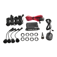
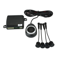
Illustrates the basic layout of sensors, ECU, and buzzers on the vehicle.

Sensor Installation

Sensor Placement Guidelines

Provides height and spacing recommendations for sensor mounting on the vehicle.

Hole Drilling

Sensor Mounting

Buzzer Installation

Wiring Diagram (Front ECU)

Wiring Diagram (Rear ECU) 1

Wiring Diagram (Rear ECU) 2

Function Test After Installation

Troubleshooting

Buzzer Not Working

Checks for buzzer issues, cable connections, and ignition status.

Damaged Sensor Detection

Identifies causes of damaged sensor alerts like loose connections or dirt.

False Warning Issues

Addresses false alarms due to incorrect sensor placement or ground detection.

Warranty Information

Related product manuals