Low Voltage Thermostat Installation continued…
Page 3 of 4 Document #1206108 Rev 7
03/19/2024
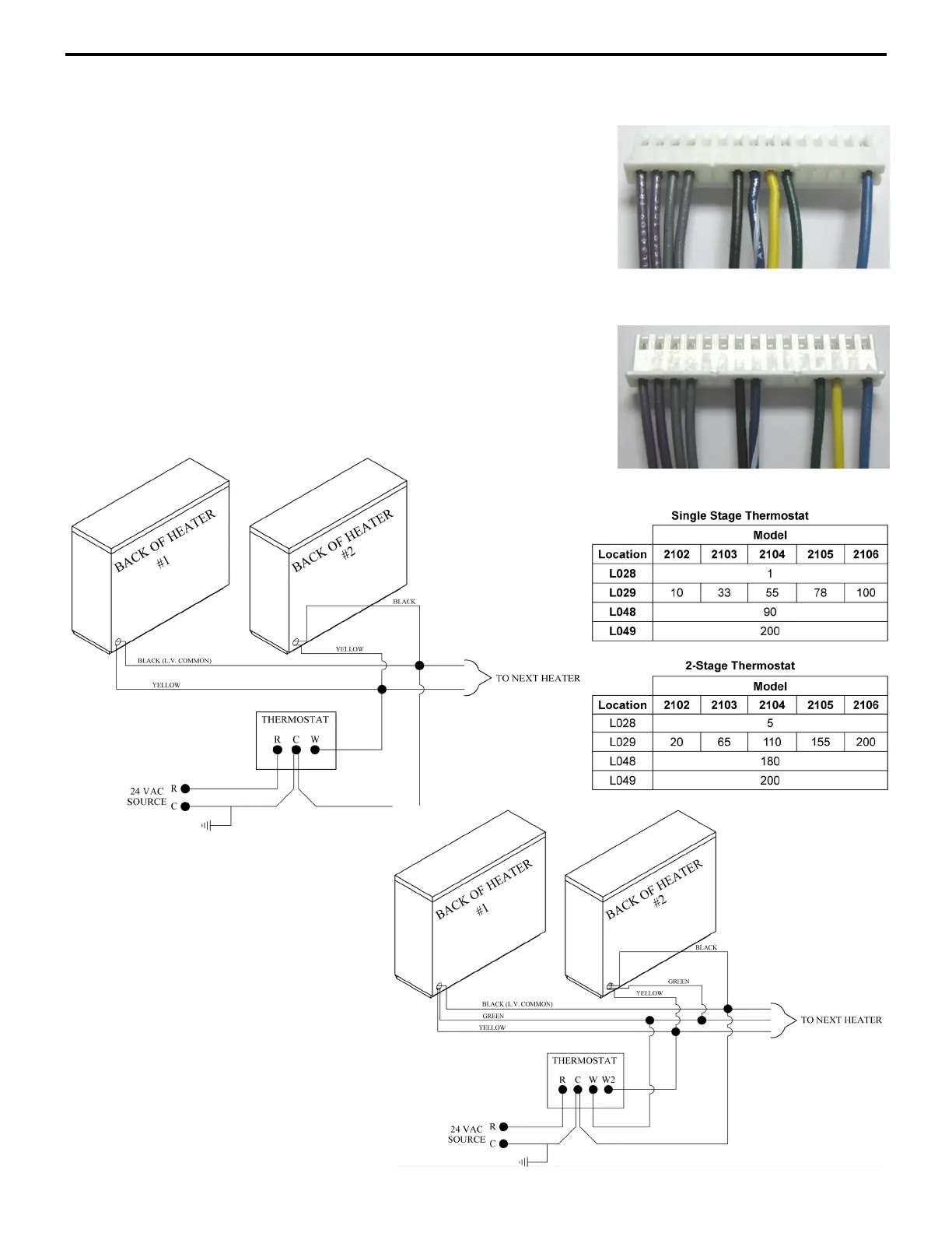
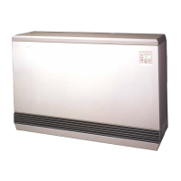
5. If using a 2-stage thermostat, move the green wire from its current
position shown in Figure 3 to the 4
th
position (Stage 1 Heat Call)
from the right on the 15-pin harness as shown in Figure 4.
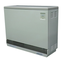
6. Connect wiring in the manner which is appropriate for the
application according to Figure 5 and 6.
7. Version 2.02 or lower only: Disconnect one of the wires from the
fan resistor on each heater.
Version 2.04 or higher only: Remove the 2 bit from the value in
Location 35 (L035). Unless other changes to the heater’s
configuration have been made, the new value will be 152.
8. Set Location 3 (L003) to a value of 32 to display heat call status
or 16 to display outdoor temperature.
9. Set the values in Location 28 (L028), 29 (L029), 48, (L048), and
49 (L049) as shown in Table 2.
15-
Figure 4
15-Pin Harness - Modified
2 Stage Wiring
2 Stage Wiring