Do you have a question about the Steg 75.4x and is the answer not in the manual?
Describes stabilized power supply, voltage range, performance, and manufacturer's right to make product modifications without prior notice.
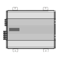
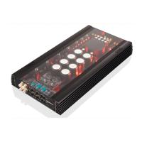
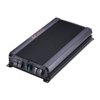
Covers optimal amplifier placement, heat dissipation, secure fixing methods, and mounting feet for installation.
Explains the meaning and operational status indicated by the amplifier's front panel LEDs.
Instructions for safely disconnecting and connecting battery terminals before any power connection work.
Details on connecting positive/negative cables, remote turn-on signal, and proper fuse installation and selection.
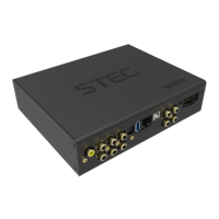
Details for connecting speakers in stereo mode, suitable for 2-4 Ohm impedance systems.
Explains mono and combined mono+stereo configurations, including impedance requirements for each.
Guidelines for shielded signal cables, routing, and using the input mode selector for signal input.
Step-by-step guide to set amplifier sensitivity for optimal sound.
How to activate, deactivate, select frequencies, and understand the cut-off slope of the internal electronic crossover.
Information on the optional ACXM2 module for precise frequency selection and its integration into the amplifier.
How control settings affect frequency response, with visual graphs illustrating various crossover filter effects.
Visual representation of different crossover filter combinations and their impact on the audio output response.
Describes the M.I.T.H.O.S. circuitry utilizing Mosfets for high output swing and maximum efficiency.
Explains the GR.I.P.S. system for noise reduction and ground loop elimination in car audio installations.
Details the P.R.H.E.S.S. technology for high-efficiency, regulated power supply in automotive applications.