INSSBF0708
3
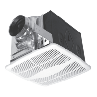
SECURING THE FAN
Locate the joist or truss.1.
On the joist or truss, mark the place where the screws 2.
will be secured.
Secure the bottom screws first (Fig. 3.1 and 3.2).3.
Secure the top screws (Fig. 3.3).4.
4
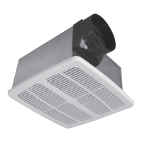
ELECTRICAL WIRING
WARNING
A) Before installing, switch off the appropriate circuit breaker/fuse in the electrical service
panel.
B) The installation must comply with local and national electrical codes.
C) The appliance must be installed by a certified electrician.
D) The unit must be properly grounded.
E) The white (neutral) wires as well as the black (hot) wires must be properly connected.
1-Removewiringcompartmentcoverandpryouttheappropriateknock-out.Thecableclamp
(included) must be inserted through the knock-out hole.
2- Using the cable clamp, run a cable from the wall switch (not included) into the fan wiring
compartment.
3- Using a connector, attach the green wire coming from the fan to the bare wire (ground)
coming from the wall switch.
4- Using connectors, attach the fan wires located inside the fan wiring compartment to the
matching wires coming from the wall switch; black to black (hot); white to white (neutral).
(Fig. 4.2)
5-Replacethewiringcompartmentcoverandsecureitwithscrews.
5
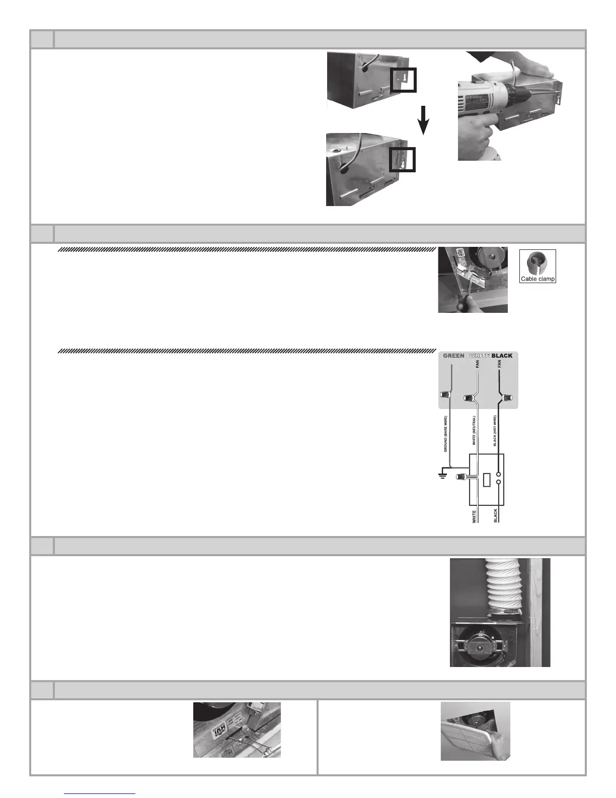
CONNECTING THE DUCTWORK
Connect the duct to the adaptor and secure the junction with duct tape or a duct clamp (not
included). Slant the duct away from the fan to avoid condensation running back into the fan
housing. For attic installations, you should use insulated ducts to reduce condensation.
IMPORTANT
• Ductworkmustcomplywithlocalbuildingcodes.
• Ductworkfromthefanshouldalwaysventtotheoutdoorsthrougheitheranexteriorwallor
roof.
• Tomaximizeairow,keepductlengthandelbowstoaminimum.
6
GRILLE INSTALLATION
Squeeze the two (2) mounting
springs and slide them into
the two (2) slots located on
the opposite sides of the fan
housing
Push the grille in place.
Fig. 4.2
Fig. 4.1
Fig. 6.1
Fig. 6.2
Fig. 3.2
Fig. 3.1
Fig. 5.1
 Loading...