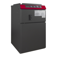
This document describes the Stelpro SFECM Series Electric Furnace, a heating unit designed for residential and commercial applications. The furnace is approved according to Canadian and American manufacturing standards, including CSA and UL.
Function Description
The Stelpro SFECM Series Electric Furnace is a central heating system designed to provide warmth and comfort. It utilizes an efficient ECM motor to maintain constant airflow regardless of static pressure variations in the ducts. The furnace offers various heating capacities, ranging from 10 kW to 30 kW, and is adaptable for horizontal, upflow, and downflow operations. It can be integrated with air conditioning or heat pump systems, and also supports the connection of electronic filters and humidifiers. The unit features a control panel with LEDs for easy diagnostic and mode selection, including continuous ventilation, continuous heating, and Eco mode.
Important Technical Specifications
The SFECM series furnaces operate on 240/208 VAC power.
Available models and their specifications:
- SFECM1021: 10/7.5 kW, 44/38 Amp, 1/2 HP, 32 1/2 in. (L), 20 in. (W), 22 1/16 in. (D), 100 lb (45 kg)
- SFECM1521: 15/11.2 kW, 65/56 Amp, 1/2 HP, 32 1/2 in. (L), 20 in. (W), 22 1/16 in. (D), 100 lb (45 kg)
- SFECM1821: 17.5/13.2 kW, 75/66 Amp, 1/2 HP, 32 1/2 in. (L), 20 in. (W), 22 1/16 in. (D), 100 lb (45 kg)
- SFECM2021: 20/15 kW, 85/74 Amp, 1/2 HP, 32 1/2 in. (L), 20 in. (W), 22 1/16 in. (D), 100 lb (45 kg)
- SFECM2321: 22.5/16.9 kW, 96/84 Amp, 1/2 HP, 32 1/2 in. (L), 20 in. (W), 22 1/16 in. (D), 100 lb (45 kg)
- SFECM2721: 27.5/20.7 kW, 119/104 Amp, 1 HP, 32 1/2 in. (L), 20 in. (W), 22 1/16 in. (D), 105 lb (48 kg)
- SFECM3021: 30/22.5 kW, 130/113 Amp, 1 HP, 32 1/2 in. (L), 20 in. (W), 22 1/16 in. (D), 105 lb (48 kg)
Optional features include a 120V motor (up to 27.5 kW), a 1 HP motor (20 and 22.5 kW), and a neutral terminal junction (SCOND).
The transformer primary is factory-set for 240 VAC operation (black and white wires), with an option for 208V connection.
The unit is equipped with a plenum temperature sensor, allowing adjustment of the plenum temperature set point from 40°C (104°F) to 70°C (158°F).
The furnace includes a filter rack, which can be installed on one of the three external sides or at the bottom of the furnace.
Electrical connections for 240 VAC can use copper or aluminum wire (75°C (165°F)), except for 27.5 kW and 30 kW models which require copper wire only.
Usage Features
Installation:
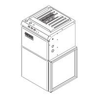
The furnace must be installed by a qualified person and connected by a certified electrician in accordance with local electrical and building codes. It requires a dry, solid base, free from flammable liquids or vapors. For vertical downflow installations, only "L" or "T" shaped plenums without openings or registers directly below the unit should be used.
Clearance:
The furnace is approved for "zero inch" clearance, meaning it can be installed directly against a wall. Ducts for models 22.5 kW and less can also have zero-inch clearance. However, ducts for models 27.5 kW and more require a 1-inch clearance for the first 36 inches, reducing to 0 inch thereafter. A minimum 24-inch clearance in front of the door is required for maintenance access.
Ducts and Filters:
Ducts should be designed for correct airflow and insulated in non-heated areas. Flexible connectors are recommended to minimize vibrations. Soundproofing material on vertical return and supply ducts, limited elbows, flexible hangers, and baffles in elbows with small curvature radii can further reduce noise. The filter rack can be installed on any of the three external sides or at the bottom.
Control Panel:
The control panel features buttons and LEDs for various functions:
- Continuous Ventilation button (1): Selects high or low speed continuous ventilation.
- Low Speed Continuous Ventilation green LED (2): Indicates low speed continuous ventilation mode is active.
- High Speed Continuous Ventilation green LED (3): Indicates high speed continuous ventilation mode is active.
- MODE button (4): Selects Standard or Eco mode.
- Standard Mode green LED (5): Indicates Standard mode is active.
- Eco Mode green LED (6): Indicates Eco mode is active.
- Continuous Heating button (7): Selects maximum or minimum continuous heating mode.
- MIN Continuous Heating green LED (8): Indicates minimum heating capacity is active.
- MAX Continuous Heating green LED (9): Indicates maximum heating capacity is active.
- THERMOSTAT yellow LED (10): Indicates a heating demand from the thermostat.
Heating Demand:
- One-Stage Thermostat: When the R-W1 circuit is closed, 100% heating activates. The blower starts at medium speed, and elements activate sequentially, limited by the plenum temperature set point. If the W1 demand persists for 30 minutes, the sequence continues as per W2.
- Two-Stage Thermostat: The furnace auto-detects two stages. W1 closes the R-W1 circuit for first-stage heating (±50%), blower at low speed, elements activate sequentially. If W1 persists for 30 minutes, it continues as per W2. R-W2 circuit closes for second-stage heating (100%), blower at medium speed, elements activate sequentially.
Continuous Heating:
Allows one or two heating elements to operate continuously (minimum or maximum). Useful for reducing temperature variations, especially at the beginning and end of the heating season. Deactivates after two hours without heating demand and reactivates with a new heating season.
Air Conditioning/Heat Pump Integration:
The furnace provides 24V power for thermostat relays (R-Y terminals) to control air conditioners or heat pumps. When R-Y terminals are activated, the blower starts at high speed.
- Type A Installation (Heat Pump After Furnace): No electric heating supplied when the heat pump is in operation (Y demand).
- Type B Installation (Heat Pump Before Furnace): Installer can select "O" for priority heating or "B" for priority cooling. The furnace compensates for heat pump capacity loss and increases heating capacity during defrosting mode, limiting plenum temperature to 40°C (104°F).
Airflow Settings:
Four potentiometers on the control card allow adjustment of airflow for heating temperature, heating ventilation, continuous ventilation, and Y ventilation. Airflows can be adjusted while the furnace is running.
Maintenance Features
General Maintenance:
Regular cleaning is essential for warranty validity. Before cleaning, cut off power at the circuit breaker/fuse. Use a soft, damp rag and non-abrasive dish soap. Avoid abrasive or chemical cleaners. For dusty locations, use a vacuum brush to remove dust from grilles.
Air Filter:
The disposable air filter should be replaced two to four times a year, or more frequently in dirtier areas. Never operate the unit without a filter. When changing the filter, check for dust accumulation on components, damaged parts, or water presence. If any issues are found, do not operate the furnace and call a qualified technician.
Blower:
The blower motor is sealed and permanently lubricated, requiring no lubrication. The blower assembly should be inspected annually for dust accumulation, even with frequent filter changes. Dust should be vacuumed out, and if removal from the furnace is necessary, this must be done by a qualified technician.
Troubleshooting:
The control card has a pilot LED (item #10 on the control panel) that blinks continuously to indicate electrical problems, aiding in diagnostics. A troubleshooting table is provided to identify defective parts or areas to check for common issues like the unit not working, continuous running, cycling under thermal protection, overheating, breaker trips, motor not working, or inability to reach desired room temperature.
Anticipator (Thermostat):
For thermostats with a heat anticipator, adjust it by setting it to the highest setting, disconnecting the W1 wire and connecting an ampmeter, increasing the thermostat set point to call for heat, letting the furnace run for 3-4 minutes to reach full capacity, and then adjusting the anticipator to the stable current reading.
High Limit Thermal Protections:
To verify, run the furnace at full capacity for 10 minutes, block air openings, and measure the supply air temperature. Elements should shut down one by one before the temperature exceeds 95°C (200°F).
Warranty:
Stelpro offers a 5-year limited warranty on products and components against defects in workmanship and materials from the date of purchase. The warranty applies only to the original purchaser. Claims require an invoice and product nameplate information. Repairs must be authorized in writing by Stelpro.