15
EHU WIRING (continued)
Trim approximately 1.5 inches of the outer jacket of the control cable (4 wire). Remove the shield material,
the support thread and cut the ground wire off as shown in figure 9. Attach electrical tape at the end of the
trimmed control cable jacket so that there is no chance for a short. Remove 0.25 inches of the insulation
from each of the individual 22 AWG wires, leaving bare copper. Tinning of the copper wire ends with solder
is not required but may be helpful in keeping the ends together while attaching the control cable wires. Fig-
ure 10 shows the control cable should look like when you are finished with the trimming. Dip each of the
copper wires into connector protector before inserting into the terminal plug. Figure 11 shows what the
connector protector will look like.
The terminal header assembly consists of the terminal header and the terminal plug as shown in figure 8.
The plug is shipped loosely attached to the header. Remove this plug when wiring and firmly plug back in
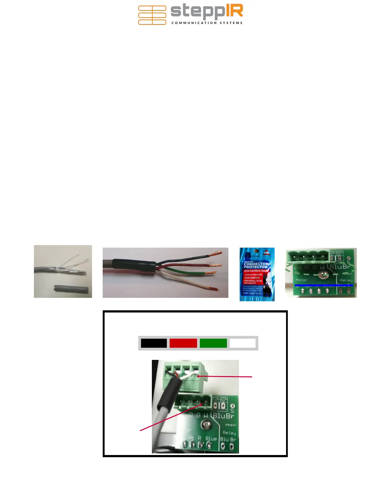
when completed. Follow the wire sequence in figure 13 for each EHU.
Be careful to ensure that there are
no bare wires protruding out from the terminal clamps, to avoid potential shorts.
The wiring sequence for each EHU is also imprinted on the PCB that the terminal header is mounted on
(located inside the EHU). Pay no attention to the second row of imprinted text, these pins are for use in
the manufacturing of the board itself and are of no use to you. Figure 12 shows a blue line crossing out the
text in question. The yellow circle shows the correct wiring sequence.
BLACK RED GREEN WHITE
4 Pin Header Wiring Sequence
TERMINAL
PLUG
TERMINAL
HEADER
FIG. 13
FIG. 9
FIG. 11
FIG. 12
FIG. 10
 Loading...


