14
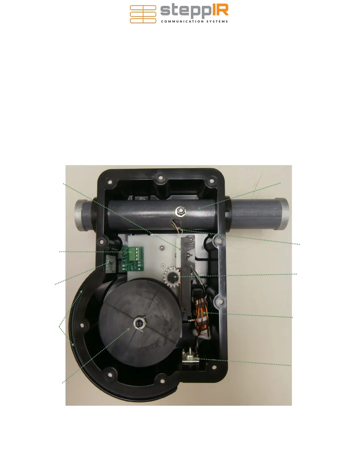
Figure 8 gives an overview of the inside of a SteppIR EHU. Wiring of each EHU will be covered in de-
tail on the following pages.
NEVER ATTEMPT ANY WIRING WHILE THE ELECTRONIC CONTROLLER IS CONNECTED TO
THE CONTROL CABLE. Even if the power is turned off of the controller, damage can occur. This is
the number one cause of antenna installation failures, so please be sure to heed the advice.
If possible, lay out the boom to measure and cut the appropriate amount of control cable for each
EHU. If laid out correctly, your measurements should be approximately:
• 124.5” from reflector EHU to Junction Box
• 51” from driven EHU to Junction Box
• 124.5” from DIR-1 EHU to Junction Box
ELEMENT HOUSING UNIT (EHU) WIRING
Control cable tray
for routing cable
out of EHU
4 position
EHU terminal header
Element support
tube
Balun (the balun
is only inside the
driven element)
Spring reel for
copper strip
SO239 connector
(for driven ele-
ment only)
Platen assembly
FIGURE 8
Serial # sticker
Copper beryllium
strip
Sprocket shaft
With 2 sprockets