13
Note: Element spacing is measured from element center line to element center line in all cases
- not from the brackets or element housing units.
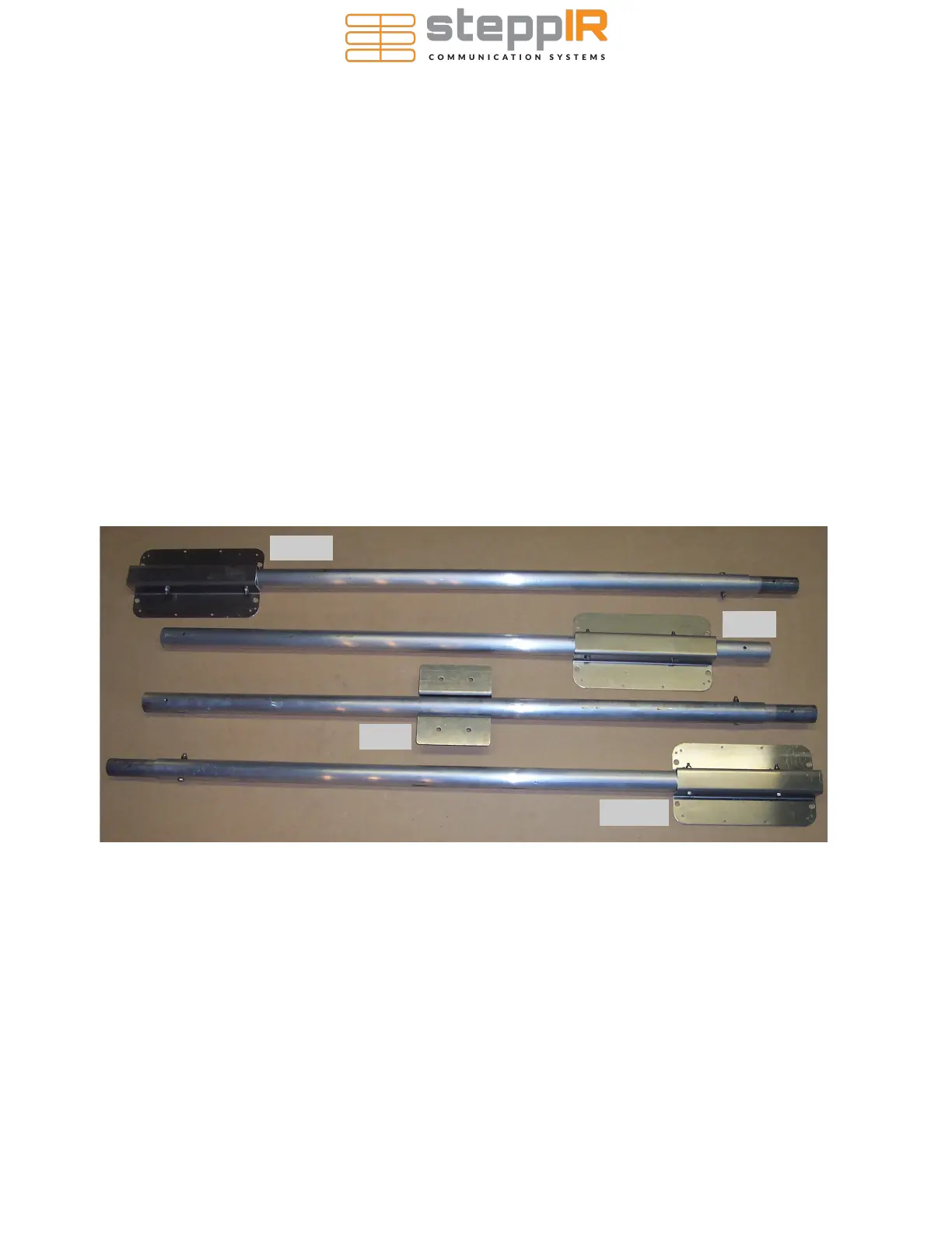
Figure 7
Director
Driven
Reflector
Return
BOOM INSTALLATION (continued)
Connect the boom by sliding the respective sections together and align the pre-drilled holes
(Figure 3 and 4). Refer to Figure 6 and figure 7 for correct configuration. It is advisable to apply a
thin film of anti-zeize (included) or Naolox (not included) to the joints before mating them.
Do not twist the aluminum excessively, as this can cause binding - the lubricant will help keep the two
pieces from seizing together. Insert the included bolts into the pre-drilled holes, and tighten the Nylok
nut securely (Figure 5). Be sure to position the bolts and nuts so that they are in the same direction as
the others.