12
BOOM INSTALLATION
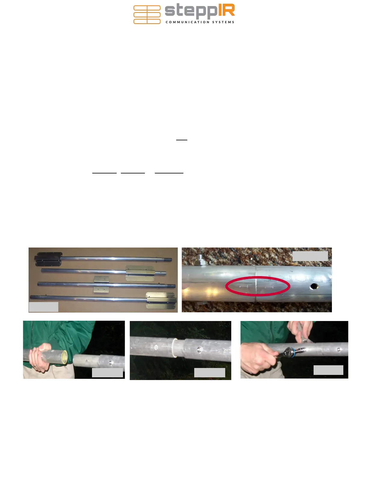
The 3 element SteppIR Yagi boom consists of four sections of aluminum tubing that are 4 feet long x 1-
3/4” OD x 1/8” wall, along with three aluminum element mounting brackets as shown in Figure 1. The
element mounting brackets are pre-installed at the factory. To assemble your antenna, you will need a
1/2” (13mm) and 7/16” (11mm) wrench and / or socket drive. We double check the fasteners for proper
tightness before shipping but it is always a good idea to check them yourself before installing the anten-
na. Put anti-seize on all bolts and screws, especially on the u-bolts. An anti-seize stick has been provided.
Assemble the boom & connect to mast plate
The boom is completely assembled and drilled at the factory to assure precision alignment. The boom,
once fitted in place on a jig, is then drilled so there is no chance for a mistake on hole placement. You
may notice in some cases that on a given splice (Figure 2) the holes on each side of the splice are at 90
degrees with each other. This is as designed and not a mistake. Pre-drilled holes are quite snug to align
almost perfectly. In some cases you may find it necessary to assist the bolts with a tap of a hammer, or
“thread” them in by turning with a wrench. If the holes are visibly out of alignment when you are assem-
bling the boom, you probably have the boom pieces put together in the wrong order - or the section of
booms without an element to boom bracket may need to be rotated 180 degrees. Each boom piece has a
number permanently written, scribed or stamped on it. Match each number with the exact same num-
ber of a corresponding boom piece. Figure 2 also shows an example of how a joint should be lined up—
in this case it is joint #1. The numbers much line up as shown in the picture.
Figure 3
Figure 5
Figure 4
Figure 2
Figure 1
 Loading...


