17
PREPARING THE CONTROL CABLE
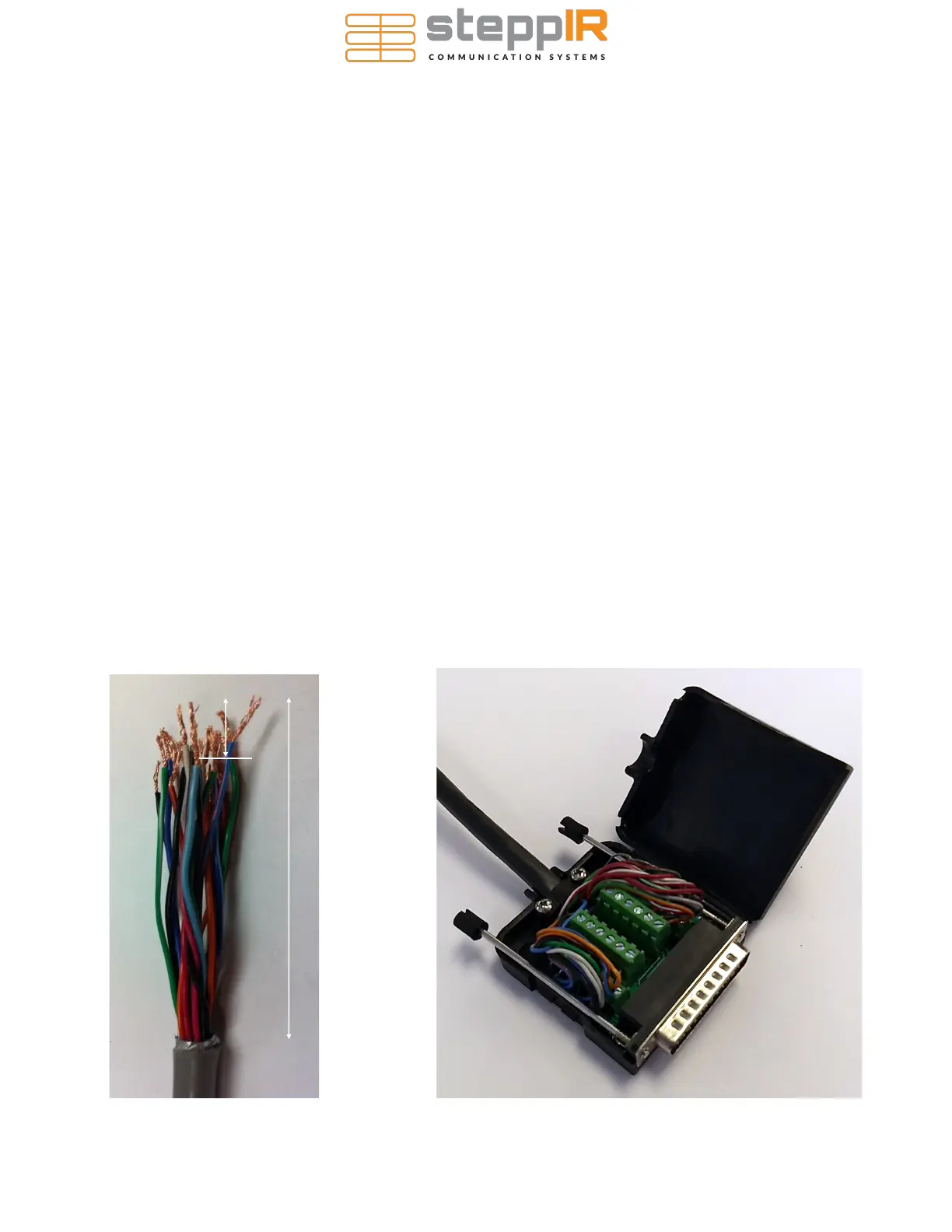
1. Strip the jacket and aluminum shielding off of the control cable as shown in figure 1, approximately
2.75” from end of control cable, being careful not to damage the individual wires.
2. Strip the plastic insulation off of each of the control cable wires, approximately 0.25” in length
should be bare wire.
CONNECTING CONTROL CABLE TO THE DB25 FIELD SPLICE
The DB25 Field replaces the standard connector with a convenient solder-less connection of the control
cable to the SteppIR controller. Follow the steps below to connect it to your control cable.
1. Apply dielectric grease to the exposed copper portion of each wire.
2. Connect each wire to the appropriate terminal and tighten using a flat head screwdriver. Note that
the terminals may be closed by default. If so, turn the terminal screw ccw ~10 turns to open it be-
fore inserting the wires. Consult the table on the next page for the correct wiring sequence.
3. Position the control cable between the cable clamp halves.
4. Tighten the two pan head screws until the cable is snug, but do not over-tighten.
5. Thread the two thumb screws into the connector face as shown in figure 2
6. Plug the DB25 splice into the back of the controller and twist the thumb-screws to secure it.
25 PIN DSUB WIRING INSTRUCTIONS
FIG. 1
2.75”
0.25”
FIG. 2
 Loading...


