31
The butt ends of the green fiberglass poles may very slightly in outside diameter. Some of them may
have been sanded, while others were not. The colors at the ends will be either natural, or black. The
difference in colors has no affect on performance. Do not be concerned if they vary slightly in tight-
ness when being installed on the EHUs. This is normal. All poles are tested at the factory prior to
shipping, however in the event the pole just won’t fit sanding it is okay. Check to be certain there are
no obstructions inside the poles—this can cause catastrophic failures!
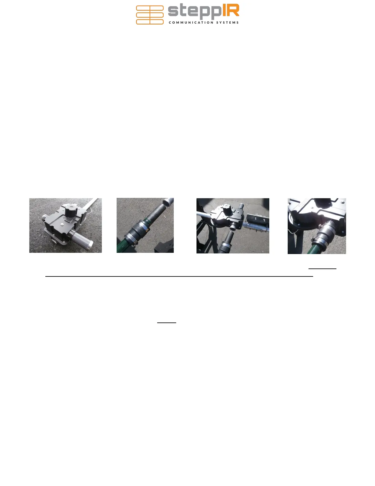
The EHTs on the EHUs have aluminum reinforcing rings attached to provide extra strength in high
wind conditions (Figure 54).
Locate the six rubber boots and repeat the following procedure for each of the six fiberglass poles.
• Place the narrow end of a rubber boot onto the butt end of an EST. Slide it about 6” out onto the
EST (Figure 55).
• Insert the butt end of that EST into one of the EHTs on an EHU, as shown in Figure 56. It is very
important to ensure that the butt end of the EST firmly bottoms out inside the EHT. Make
sure the EST is seated all the way into the EHT. Then push the rubber boot firmly onto the
EHT until the hose clamp is past the aluminum ring and will clamp down onto the fiberglass
EST. The correct mounting position of the rubber boot is shown in Figure 57. Note that current
production antennas now have a narrower aluminum ring (.4”). It is imperative that the stainless
steel hose clamp be located so that the clamp on the outside of the rubber boot on the EHU
side of the connection is completely PAST the the aluminum reinforcing ring. This ensures
that the hose clamp can grip onto the fiberglass and the ring will prevent the rubber boot
from ever coming off.
• Firmly tighten both stainless steel hose clamps, one over the EHT and the other over the EST.
Then test the connection by pulling and twisting it. There should be no slippage at the joints.
NOTE: You should re-tighten each clamp a second time (at least 30 minutes after the first time you
tightened them) before raising the antenna to the tower, to be sure that there has been no cold
flowing of the PVC material on the rubber boot.
Figure 54
Figure 55
Figure 56 Figure 57
Attach the non-loop Fiberglass Element Support Tubes to the Element Housing Units
 Loading...


