34
ELEMENT TRUSS SUPPORT
• Check and inventory that you received all the parts for the 39 ft 40M/30M truss option.
• Be sure to use anti-seize on all of the stainless steel fasteners in this step. Failure to do so will potentially
cause them to seize/gall.
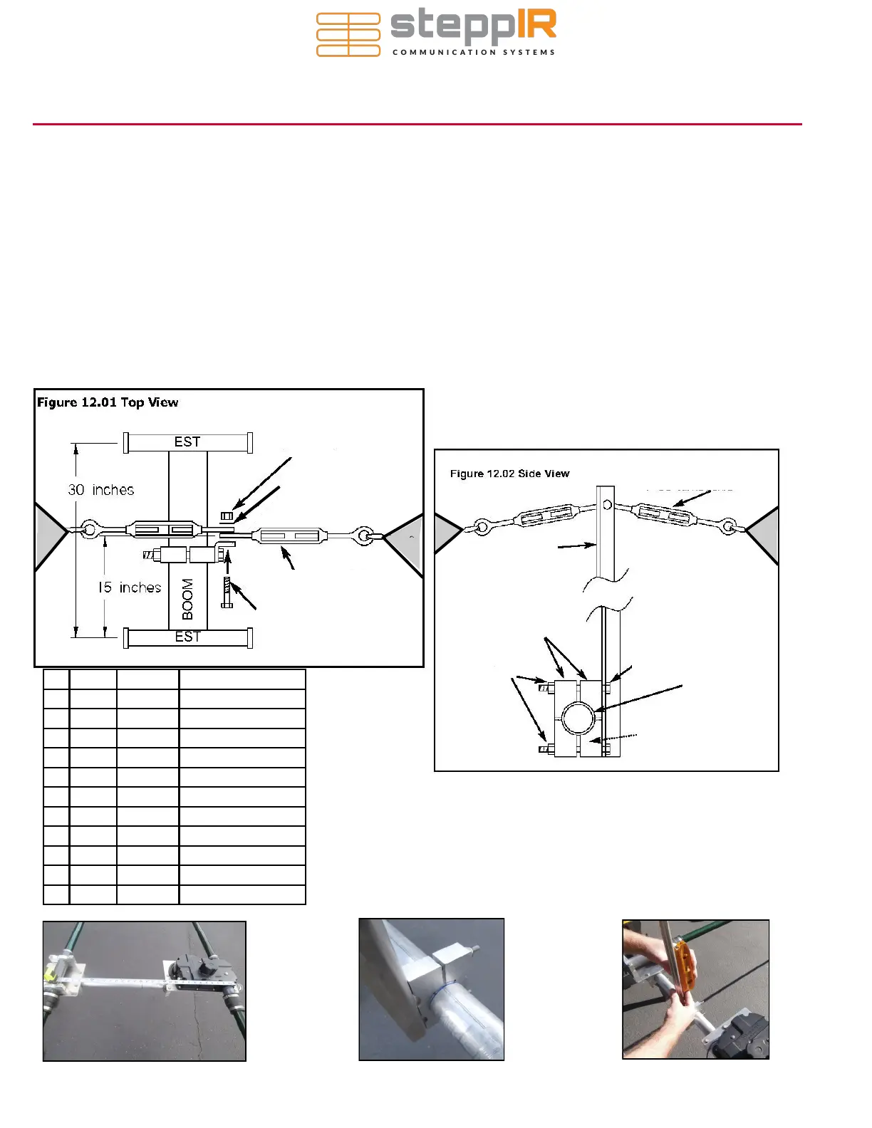
1. Secure the element truss support (PN 10-1054-01) to the aluminum saddles so that the head of the 5/16”
bolt are on the truss support side as shown in Figure 12.02. Secure the truss support and saddle assembly
around the boom so that its halfway between the driven EST and return EST as shown in Figure 12.01.
NOTE: The DB18E truss support for the DRIVEN element is completely different than all of the
other antenna models. Refer to page 9 for these instructions. For the two end elements on the
DB18E, follow instructions on this page (Pg 10). It is not critical which side of the boom the truss sup-
port is on. Use the boom as a line to sight in the truss support so that it is perpendicular to the boom. Level
the support before tightening as shown in figure 14.03. After tightening, insert a set screw into the exposed
saddle and tighten.
Figure 14.01
Figure 14.02
Figure 14.03
A
B
C
D
G
F
E
H
I
J
K
Key QTY Part # Description
A 1 60-0030 1/4” SS nylock nut
B 2 60-0033 5/16” SS washer
C 2 60-0083 4” SS turnbuckle
D 1 60-0110 1/4” X 1-1/4” SS hex bolt
E 1 10-1054-01 30m / 40m truss support
F 2 10-1601-03 1-3/4” Aluminum saddle
G 2 60-0046 5/16” SS nylock nut
H 2 60-0083 4” SS turnbuckle
I 2 60-0065 5/16” X 3-1/2” SS hex bolt
J 1 N/A Antenna Boom
K 2 10-1601-22 2” saddle
 Loading...


