36
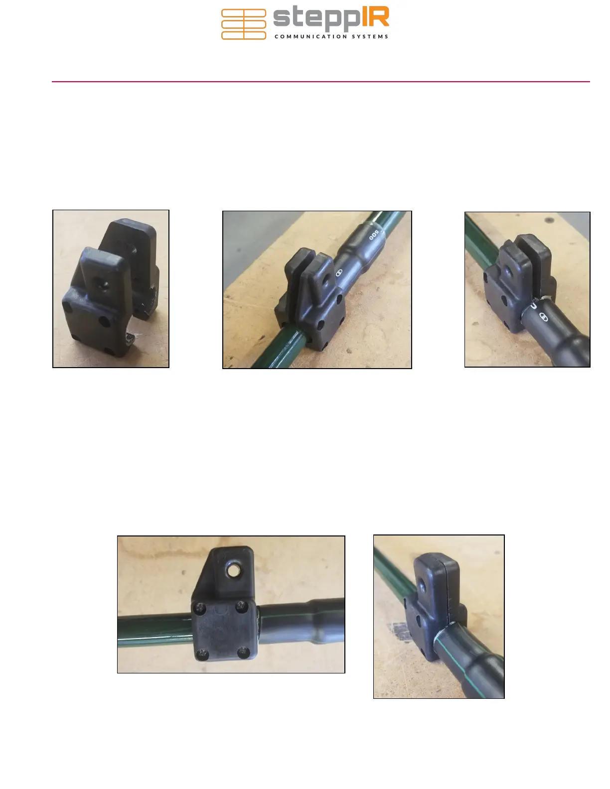
1. Each element truss coupler consists of 2 halves as shown in figure 2.01. The element truss couplers (PN
10-1510-01) are used for fastening the Dacron rope to the last section of the telescoping poles. Figure
2.12 on page 8 provides an expanded view of a truss element assembly.
2. Position each coupler so that it is flush to the polyolefin heat shrink on the smallest joint of the telescop-
ing pole as shown in figure 2.02 and 2.03. DO NOT place the coupler over the polyolefin heat shrink
or it will not seat properly. Figure 2.12 on page 8 shows the location respective to the telescoping pole
to mount the truss coupler.
3. Insert the 6-32
x 7/8” stainless
steel screws
(60-0014 -01)
through the
round opening
and place the 6-32
nylock nuts (60-0014) in the hex opening of the element truss coupler. These are handy for holding the
#6 Nylock nut (PN 60-0014) when tightening, but you will need to position your finger over the nut to
keep it from spinning when you thread on each of the #6 x 7/8” pan-head machine screw (PN 60-0014-
01). Tighten the stainless steel screws and Nylock nuts. Be sure your couplers are perpendicular to the
pole and level before final tightening. Figure 2.04 and figure 2.05 show the coupler when tightened.
They should be flush or have a small gap between the couplers.
Figure 2.01
Figure 2.02
Figure 2.03
Figure 2.04
Figure 2.05
ELEMENT TRUSS COUPLER
 Loading...


