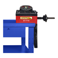
The device described in the manual is a Wheel Balancer, model ST-1110, designed to correct imbalances in vehicle wheels. This process is crucial for preventing issues such as wheel jumping, steering wheel shaking, damage to steering system components, and increased accident risk. The machine utilizes a large-scale integrated (LSI) circuit for efficient data processing and calculation of balancing results.
Function Description
The wheel balancer operates by measuring the imbalance of a wheel and then guiding the user to attach appropriate weights to correct it. It supports various balancing modes, including dynamic, static (ST), and several ALU modes (ALU-1, ALU-2, ALU-3, ALU-S) for different rim structures. The device features a user-friendly LED display and control panel with buttons for inputting rim data (distance, width, diameter) and selecting operational modes.
Key functions include:
- Balancing Modes: Dynamic balancing for standard rims, static balancing for rims where weights can only be attached to the center (e.g., motorcycle rims), and specialized ALU modes for different aluminum rim designs.
- Imbalance Optimization: If the imbalance exceeds a certain threshold (e.g., 30 grams), the machine can guide the user through an optimization process to minimize the required weight. This involves marking the tire and rim, rotating the tire on the rim, and re-measuring.
- Self-Calibration: The machine has a self-calibration feature to ensure accuracy, especially after transportation or prolonged use, which might alter system parameters. This involves attaching a known 100-gram weight and performing a calibration spin.
- Splitting and Hiding Wheel Weight: In ALU-S mode, the device allows for splitting a single weight into two smaller weights to be placed behind spokes, effectively "hiding" them for aesthetic purposes.
- Recalculation: The machine can recalculate imbalance values even after a balancing spin, allowing users to input or correct rim data retrospectively without needing another spin.
- Self-Diagnosis: A diagnostic function helps identify faults in the machine's signals, sensors, and circuit boards, aiding in troubleshooting.
- Unit Conversion: The device allows changing the unit of weight measurement between grams and ounces, and rim measurements between inches and millimeters.
- Adjustable Settings: Users can adjust the minimum imbalance displayed (showing 0 if below a set threshold), keyboard sound effects, and screen brightness.
Important Technical Specifications
- Maximum Wheel Weight: 65 kg
- Power Source: DC12V 1A
- Rotating Speed: 120 r/min
- Sequence Length: 8 seconds
- Rim Diameter: 10″ – 24″ (256 mm – 610 mm)
- Rim Width: 1.5″ – 20″ (40 mm – 510 mm)
- Noise Level: <70 dB
- Machine Weight: 30 kg
- Working Environment:
- Temperature: 5 – 50 degrees Celsius
- Height above sea level: ≤ 4000 m
- Humidity: ≤ 85%
The electrical system comprises an LED screen, keyboard, and an LSI-circuit (MCU processor) as the control unit. It includes a rotation speed and location detection system (gears and optical electronic coupling), a two-step asynchronous motor with its control circuit, and horizontal and vertical pressure sensors.
Usage Features
The operation of the ST-1110 wheel balancer is guided by its LED display and control panel.
- Installation: The machine should be installed on a stable surface at least 60 cm high, secured with three M8 screws. The shaft must be correctly installed and tightened.
- Wheel Attachment: Users select an appropriate cone for the rim's center hole. Wheels can be attached in either a positive (most common for steel and aluminum rims) or negative position (for damaged outer rims or thick steel rims) to the shaft. It's crucial to ensure the wheel can rotate freely after attachment.
- Data Input: After initialization, the machine enters dynamic balancing mode. The user inputs the rim's distance, width, and diameter using a measuring arm and corresponding buttons ([a↑]/[a↓], [b↑]/[b↓], [c↑]/[c↓]).
- Balancing Process:
- The user rotates the wheel by hand. The display will show "RUN ---" as it spins, then "STOP" when it halts, displaying imbalance data.
- The user slowly rotates the wheel to align inner and outer indicators (10 and 11 on Fig 3) with the 12 o'clock position.
- Weights corresponding to the displayed values are attached to the inner and outer edges of the rim.
- Another manual spin is performed to confirm balance.
- Mode Selection: The [MODE] button cycles through dynamic, static, and ALU balancing modes.
- Button Combinations: Specific button combinations (e.g., [FINE] + [SET] for self-calibration, [FINE] + [a↑] + [a↓] for unit toggle, [FINE] + [MODE] for machine settings) provide access to advanced functions.
- Safety: The manual emphasizes wearing appropriate clothing to avoid entanglement and restricts operation to the designated user. Only fingers should be used to press buttons, not tools.
Maintenance Features
The manual outlines both daily and professional maintenance procedures to ensure the longevity and accuracy of the wheel balancer.
Daily Maintenance:
- Power Off: Always turn off the machine before any maintenance.
- Belt Tightness: Adjust the belt tightness as needed.
- Electrical Connections: Check all electrical connections for security.
- Main Shaft Bolt: Ensure the main shaft bolt is tight; use an Allen key if necessary.
- Fast-Locking Nut: Verify that the fast-locking nut securely locks the rim to prevent rotation on the shaft during operation.
Professional Maintenance:
- Troubleshooting: If persistent functional errors occur that cannot be resolved by self-calibration, professional service is required.
- Sensor Adjustment/Replacement: Adjusting or replacing power sensors (No. 6, 7) involves unscrewing specific nuts (No. 1, 2, 3, 4, 5), detaching the old sensors, installing new ones according to the diagram (Fig 33), and carefully fastening the nuts. Attention to sensor direction is critical.
- Circuit Board Replacement: Replacement of the circuit board must be performed by a professional.
Troubleshooting Table (Vianmääritystaulukko):
The manual includes a comprehensive troubleshooting table that lists error codes (Err 1 to Err 7), their meanings, probable causes, and suggested fixes. For example:
- Err 1 (Main shaft not spinning): Causes include computer board fault or connection disturbance. Fixes involve checking/changing the computer board or cable connections.
- Err 2 (Rotation lower than 60r/min): Causes include position sensor fault, improperly attached wheel, or computer board fault. Fixes involve changing the position sensor, attaching the wheel properly, or changing the computer board.
- Err 3 (Miscalculation): Caused by too high imbalance. Fix is to repeat self-calibration or change the motherboard.
- Err 6 (Data loss): Caused by failed self-calibration or computer board fault. Fixes involve repeating self-calibration or changing the computer board.
The manual also provides a "Hint" for checking the accuracy of the wheel balancer by performing a self-calibration with a 100-gram weight and comparing measured values.