1. Make sure key switch is in the OFF
position.
2. Remove cover from base unit by
applying pressure to the key barrel.
Ensure that the tamper screw located
on the bottom right hand side is removed
by using the tamperproof tool provided.
3. Set switches, on circuit board, to desired
alarm settings (figure 4 see over).
4. Mount base unit on or next to door using
the 2 fixings provided. (See Dia. A for
recommendation*). Reed switch mounting
locations can be moved to the four positions
shown in Dia. A. If mounted next to door,
route reed switch wire through knockout in
bottom of housing as shown in figure 2.
5. Mount magnet on door frame (or door if
unit is mounted next to door) using screws
provided. When mounting on metal doors
or door frames, use plastic spacer provided.
Reed switch and magnet must be within
13mm/1/2" when door is closed. Please refer
to figures 5, 6 and 7 for other mounting options.
6. To fix the cover to the base unit, hooks
can be found on the inside top edge of the
cover. Insert the hooks into the slots provided
on the edge of the base unit (see Dia. B) and
snap the cover down until it clicks into place.
Using the tamperproof tool provided insert
and tighten the screw to secure the cover to
the base (see Dia. C).
7. REMOVING THE COVER FROM THE BASE
Remove the tamper screw located on the bottom
right hand side with the tamperproof tool provided.
Apply pressure to the key barrel. Keep the
tamperproof tool safe for future servicing and
battery change.
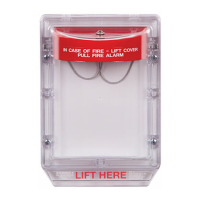
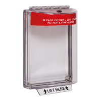
EXIT STOPPER
A completely self-contained security system that provides a highly effective, extremely versatile and
inexpensive way to help prevent unauthorised use of fire/emergency doors. The EXIT STOPPER is
supplied with an installation kit and 9v alkaline battery. It also incorporates a key override facility for
authorised use.
SCREW
6 x 1 1/4 in.
(2) PROVIDED
SHOWN
BOTTOM SURFACE AS
WIRES THROUGH NOTCH O N
AND ROUTE REED SWITCH
REMOVE FRONT COVER
(USED AS NECESSARY)
SPACER S
NOTE: 2 SPACERS UNDER BOTH
MAGNET AND REED SWITCH
MUST BE USED ON STEEL DOORS
VIEW SHOWING MAGNET INSTALLATION
NB: FITTING UNIT AWAY FROM DOOR (OPTIONAL)
MAGNET
13mm [1/2 in.]
MAXIMUM GA P
FIGURE 2
INSTALLATION DATA FOR THE STI-6400 & STI-6400/WIR
Housing 3mm 1/8" polycarbonate
Power Source 9 VDC Alkaline
Sounder Output 95 dB - low/105 dB - high
Relay Output 9 VDC, 40mA
Dimensions 136mm/5.35" h x 136mm/5.35" w x 50mm/1.97" d
Standby Current 10uA
Alarm Current 200mA
SPECIFICATIONS
STI-6400 Exit Stopper
STI-6402 Exit Stopper Double Door
STI-6400/RK Remote Kit
STI-6400/RS Remote Sounder
PART No.
EXIT STOPPER PART NUMBERS
PRE INSTALLATION CHECKLIST
IMPORTANT NOTICE: If you have purchased a STI-6400/WIR model, before installation you will need
to ‘learn’ the transmitter to the 8 channel receiver. Please refer to the Quick Setup Guide. Once‘learned’,
follow steps 1-7 opposite.
DO YOU WANT HIGH OR LOW SOUNDER OUTPUT?
The Exit Stopper is factory set for HIGH sounder output (105 dB). To change the unit to a LOW output
(95 dB), locate JP2 and move to the OFF position.
DO YOU WANT THE EXIT STOPPER TO ALARM IMMEDIATELY?
The Exit Stopper is factory set to arm immediately after the key is turned to the ON position. You can
change this to a 15 second arming delay. This feature allows an authorised key holder to turn the unit
on and then exit through the door before the unit arms. To set a 15 second arming delay move jumper
JP7 to the OFF position.
DO YOU WANT THE EXIT STOPPER TO ACTIVATE IMMEDIATELY THE DOOR IS OPENED?
The Exit Stopper is factory set to activate immediately the protected door is opened. The unit can be
set for a 15 second delay. This would allow an authorised key holder to open the door and turn the Exit
Stopper off before it activates. To set to a 15 second activation delay move the jumper to JP5 to the ON
position.
SOUNDER OUTPUT OPTIONS
The Exit Stopper is factory set to sound for 30 seconds once activated. There are three other settings,
180 seconds, continuous and 5 beeps.
STI F021
STI CO23/A
STI BAT1
STI L6400
ACCESSORIES
DIA. B
PART No.
PC BOARD
REED SWITCH
REED SWITCH MOUNTING
KEY
(2) PROVIDED
OUTER COVER
NOTE: TO SELECT ALARM OPTIONS,
REMOVE OUTER COVER AND FOLLOWING
THE SWITCH SETTINGS CHART, SHOWN ON
REVERSE SIDE, CHOOSE THE ALARM
OPTIONS SUITABLE FOR EACH INSTALLATION.
SCREW #8 x 1 in.
(2) PROVIDED
USING BACK PLATE AS
TEMPLATE MARK AND DRILL
(2) 4.7 mm [3/16 in] DIA. HOLES
RAWL PLUG
(2) PROVIDED
SHOWN IN FACTORY
INSTALLED POSITION
9 VOLT
ALKALINE
BATTERY
KEY SWITCH
4 FIXING HOLES
DIA. A
SLOT
PEGS. (4 OPTIONAL POSITIONS)
SLOT
SCREW
TAMPER-PROOF
(1) PROVIDED
TAMPER
PROOF TOOL
(1) PROVIDED
DIA. C
FIGURE 1
*
*
*recommendation
for the fixings
ID6400-6400WIR · Revised 01/17 -001 · Printed in England
SLOT
HOOK
VIEW SHOWING HOW TO FIX THE COVER TO THE BASE
FIGURE 3
Emergency Exit Warning Sign
9 V Battery
Spare Keys
Tamperproof Tool
DESCRIPTION DESCRIPTION
www.acornfiresecurity.com
www.acornfiresecurity.com