SPECTRE Access UHF
Read only
Installation procedure
UHF SPECTRE Access
Lecture seule
Notice d’installation
UHF SPECTRE Access
Solo lectura
Manual de instalación
© STid - 20 PA des Pradeaux FR13850 Gréasque - NI1127X03 - Page 1 sur 15 - Ed. 16/05/2019
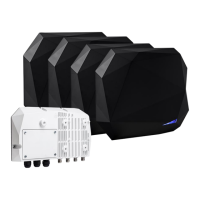
SPECTRE Module Access - SMA
SPECTRE Reader Access - SLA
Frequency Band: 865 - 868 MHz
SMA-R41-A-U04: TTL
SMA-R42-A-U04: RS232
SMA-R43-A-U04: RS485
Frequency Band: 865 - 868 MHz
SLA-R41-A-U04: TTL
SLA-R42-A-U04: RS232
SLA-R43-A-U04: RS485
Frequency Band: 902 - 928 MHz
SMA-R51-A-U04: TTL
SMA-R52-A-U04: RS232
SMA-R53-A-U04: RS485
Frequency Band: 902 - 928 MHz
SLA-R51-A-U04: TTL
SLA-R52-A-U04: RS232
SLA-R53-A-U04: RS485
Power Supply Characteristics - SMA /SLA
Use an AC/DC power supply LPS type, Limited Power Source (as per IEC EN 60950-1 Ed2) or ES1 type, PS1 (as per IEC EN 62368-1) for main supply and for
an eventual V+/V-.
Main power supply: Range +9 Vdc up to +36 Vdc Typical: 12 Vdc
Consumption: Typical: 1A under +12 Vdc Max: 1.5A under +12 Vdc
Characteristics - SMA / SLA
Communication: RS485 (L+ & L-) / RS232 (TD & RD) / TTL (Wiegand / Clock & Data)
Pin out: Removable connectors 3x4 pins and 1x8 pins, thread 3.81 mm / 0.149 in
Temperature: -25 to +60 °C / -13 to +140 °F
Protection: IP66 level
Chip: EPC1 Gen2 (ISO 18000-63) - 1 to 62 bytes max
I/O: 4 optocoupled inputs and 4 optocoupled outputs
Module LED: 1 red LED: presence of power supply and 1 green LED: activity on Reader / host link
Antenna LED: 7 configurable colors (red, green, blue, orange, purple, turquoise, white)
Recommended Cables - SMA / SLA
Use a multi-conductor shielded twisted pair cable.
Max length RS485: 3 280.84 ft / 1000 m at 9600 baud.
Max length RS232: 49.21 ft / 15 m.
Wiegand / Clock & Data:
1 pair AWG24 – 30 m / 98.43 ft max
2 pairs AWG24 – 60 m / 196.85 ft max
3 pairs AWG24 – 100 m / 328.08 ft max
1 pair AWG20 – 50 m / 164.04 ft max
2 pairs AWG20 – 100 m / 328.08 ft max
Recommendations - SMA / SLA
▪ Install the module/reader away from computer transmission cables or from power sources (ex: RJ45, sector…).
The disruptions that they can cause can vary according to their radiation power and their proximity.
▪ Use a filtered and regulated power supply.
▪ Antennas connected to different modules/readers may interfere with each other. Move them away from each other.
▪ A power supply which provides 1.5 A min under +12Vdc is recommended.
If the IN/OUT are powered by the module, use a 2A min under +12Vdc power supply.
▪ Users must not remain within a range of less than, 34 cm / 13.39 in from an antenna for an extended period of time as per EN50364 applicable to this
type of device.
▪ Apart from the hatch the module housings must not be opened.
▪ Before any service operation you must de-energize reader.
▪ Check that the hatch seal is correctly positioned before closing.
▪ Do not remove the caps of unused
cable glands:
▪ Do not remove the caps from the unused
RF connectors:
▪ Install the module/reader with the word UP
facing upwards so that the connectors are down:
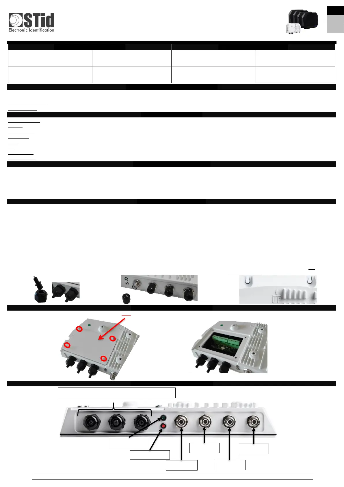
Host Connection Access - SMA / SLA
In order to access the module/reader connectors, open only the hatch provided for this purpose by unscrewing the 4 captive screws without removing them from
the hatch.
Front View of the Module - SMA / SLA
Cable glands (Data Bus-Power sup. - Input/Output)
 Loading...