17 West St., W. Hatfield, MA 01088 | 800.582.8423 | 413.247.3380 | fax 413.247.3369 | info
@
stiebel-eltron-usa.com | www.stiebel-eltron-usa.com
CW
R
RC840T-120
1
2
R
C
W
Low Voltage
Thermostat
L
120 VAC
15 A
Single Pole
Circuit Breaker
N
CK/CKT/CNS
120 VAC Units
wiring the unit in this manner.
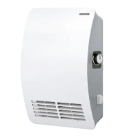
To install one or more CK/CNS heaters to a low voltage
thermostat, each heater must have its own transformer/
relay device. This device will be connected at a junction
box near the heater and wired both to the heater and to
the load panel. Please see figures 3, 4, and 5 for wiring
diagrams illustrating the manner in which to hook up a
Fig. 3: 120 V heater with low voltage thermostat.
CW
R
RC840T-240
1
2
R
C
W
Low Voltage
Thermostat
L1
240 VAC
15 A
Double Pole
Circuit Breaker
L2
CK/CKT/CNS
240 VAC Units
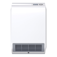
Fig. 4: 240 V heater with low voltage thermostat.
CW
R
RC840T-240
CW
R
RC840T-120
1
2
R
C
W
Low Voltage
Thermostat
1
2
L1
240 VAC
15 A
Double Pole
Circuit Breaker
L2
L
120 VAC
15 A
Single Pole
Circuit Breaker
N
CK/CKT/CNS
240 VAC Units
CK/CKT/CNS
120 VAC Units
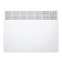
Fig. 5: Mulple heaters, both 120 V and 240 V, connected to single low voltage thermostat.
single 120 V heater, a single 240 V heater, and multiple
heaters, to a low voltage thermostat. Be aware that, as
with most transformer/relay devices, there are both 120
V and 240 V versions of the RC840T, so be sure to select
the appropriate device for your application.
 Loading...