11
English
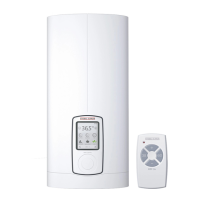
• Two-handle pressure valves
• Kitchen valve WKMD
Part no. 07 09 17
• Bath valve WBMD
Part no. 07 09 18
• Installation accessories
• Under-worktop set – unfi nished
walls
Best.-Nr. 07 05 65
Connections for finished walls, G 3/8”,
top.
• Bausatz 2 Stück Wasser-Stopfen
G ½
Part no. 07 43 26
Required with third party pressure val-
ves (
P
a).
Note: Not required for Stiebel Eltron
valves WKMD and WBMD.
• Installation set – fi nished walls
Part no. 07 40 19 (
Q
a)
consisting of:
– 2x water plugs G½”.
– 2x union nuts ½” with insert for sol-
dered fitting Ø 12 mm.
• Universal Montagerahmen
Part no. 22 02 91
consisting of:
– mounting frame with
– electrical wiring.
This set creates a gap of 30 mm bet-
ween the equipment back wall and
the installation wall. This enables the
electrical connection to be routed over
unfinished walls at any point behind the
equipment. It increases the equipment
depth by 30 mm and reduces the pro-
tection level to IP 24 (splash-proof).
• Offset installation set – unfi nished
walls
Part no. 22 02 90
consisting of:
– universal mounting frame (see part
no. 22 02 91 for specification).
– pipe bends for installation at existing
gas water-heater connections (cold
water left and hot water right).
• Gas water-heater replacement set
Part no. 22 05 10
consisting of:
– universal mounting frame (see part
no. 22 02 91 for specification).
– pipe bends for installation at existing
gas water-heater connections (cold
water left and hot water right).
• Rohrbausatz DHB-Austausch
Part no. 15 98 76
consisting of:
– 2x plug-in water coupling.
Water connections in the instantaneous
water heater, suitable for existing DHB
plug-in water connections.
• Load circuit breaker LR 1-A
Part no. 00 17 86
Priority control of the DBH-E electronic
for imultaneous operation of e.g. electric
storage heaters.
For connection of the LR 11-A, see
N
.
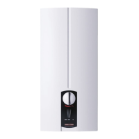
8. Special accessories
Table 6
7. Troubleshooting by the contractor
Fault / Diagnostic “traffi c light” display* Cause Remedy
Flow rate too low Shower head/percolators scaled up
Contamination
Descale and replace if necessary.
Clean strainer (
G
19).
Heating does not switch on/no hot water The air sensor senses the presence of air in the
water and briefly switches the heater off
Equipment starts again after a few seconds.
No hot water MCB tripped/fuse blown Check fuse/MCB (fuse box).
No “traffic light” display Safety pressure limiter AP 3 has tripped
Faulty PCB
Remove the cause of fault (e.g. faulty pressure
washer). Press button on safety pressure limiter
(
A
12), but only after isolating the equipment
from the electrical supply.
Test the PCB (
A
9), replace if necessary.
No hot water and flow rate > 3 l/min
“traffic light”
display: green flashing or constant
illumination
One phase down
Faulty PCB
Check fuse/MCB (fuse box).
Test the PCB (
A
9), replace if necessary.
No hot water and flow rate > 3 l/min
“traffic light”
display: constant yellow indicationt
green flashing
High limit safety cut-out (STB) tripped or cable
break
Heating system faulty
Faulty PCB
Check the high limit safety cut-out and replace if
necessary (
A
17).
Test the heating system resistance (
A
14) and
replace if necessary.
Test the PCB (
A
9), replace if necessary.
No hot water
“traffic light”
display: red indication
green flashing
Cold water supply temperature > 35 °C
Flow rate > 25 l/min
Cold water sensor faultyt
Reduce the temperature of the cold water sup-
ply to the equipment.
Reduce the flow rate to the equipment.
Test the PCB (
A
9), replace if necessary.
* LED diagnostic
"traffi c light"
red
yellow
green
10. Guarantee
9. Environment and
recycling
Dispose of packing material and appliances
The dispose of the packing material and the
appliances must be done according to the lo-
cal recycling laws and regulations.
For guarantees please refer to the pespec-
tive terms and conditions of supply for your
country.
The installation, electrical connection
and fi rst operation of this appliance
should be carried out by a qualifi ed installer.
The company does not accept liability for
failure of any goods supplied which accor-
dance with the manufacturer‘s instructions.
 Loading...