10
6. Troubleshooting by the user
Table 5
5. Specifi cation and application areas for contractors
* Values for pressure losses also apply for minimum flow pressure according to DIN 44851/flow volume for heating from 10 ºC to 60 ºC (∆ϑ 50 K).
On the basis of DIN 1988 Part 3, Table 4, pressure loss of 0.1 MPa (1 bar) is recommended with regard to the dimensioning of the pipe network.
Tabelle 3
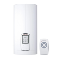
Type DHB-E 18 Si
electronic
DHB-E 21 Si
electronic
DHB-E 24 Si
electronic
DHB-E 27 Si
electronic
Rated outputl kW 18 21 24 27
Pressure drop*
with DMB
without DMB
MPa (bar) / l/min
MPa (bar) / l/min
0,08 (0,8) / 5,2
0,06 (0,6) / 5,2
0,1 (1,0) / 6,0
0,08 (0,8) / 6,0
0,13 (1,3) / 6,9
0,10 (1,0) / 6,9
0,16 (1,6) / 7,7
0,12 (1,2) / 7,7
Flow rate limiter (DMB) l/min
color
7,5
blue
7,5
blue
8,5
green
8,5
green
Capacity 0,4 l
Typ e closed
Rated overpressure 1 MPa (10 bar)
Weight 3,6 kg
Protection class as per DIN EN 60335 1
Protection mode as per EN 60529 IP 25
Test marks see unit rating plate
Water connection (external thread) G ½
Electrical connection 3/PE ~ 400 V
VDEW approval present
Heating system bare wire
Area of use especially for water with high lime content
Range of use for specific electrical
resistance/conductivity
see Table 4
Flow volume „On“
≥ 3,0 l/min
Fault Cause Remedy
The heating system inside the DHB-E electronic
will not start although the DHW valve is fully
open.
No voltage User / Contractor:
check the fuses in your fuse box.
The start-up volume required to start the heater
has not been reached. Contamination or scaling
of percolators in the valves or shower heads
User / Contractor:
clean and/or descale
Heating system faulty Call service department / contractor:
Test heater and replace if necessary
Intermittent cold water The air sensor senses the presence of air in the
water and briefly switches the heater off
Equipment starts again after a few seconds
5.1 Specifi cation (details listed on the type plate apply)
5.2 Area of application
Area of application for instantaneous water heaters, related to the specifi c electrical resistance
of the water/specifi c electrical conductivity.
* The values for the specific electrical resistance or electrical conductivity respectively are to be
determined on a regionally divergent basis, at different temperatures. This must be taken into
account in the assessment.
Table 4
Details as Ranges of use for different references temperatu-
res * from water analysis
Normes details
at 15 °C at 20 °C at 25 °C
Specifi c electrical resistance
corresponding to
Specifi c electrical conductivity
≥ 900 Ωcm
≤ 111 mS/m
≤ 1110 µS/cm
≥ 800 Ωcm
≤ 125 mS/m
≤ 1250 µS/cm
≥ 735 Ωcm
≤ 136 mS/m
≤ 1360 µS/cm
 Loading...