
J
Jason MayerAug 1, 2025
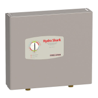
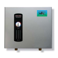
Why is there no hot water from my STIEBEL ELTRON Hydro-Shark SH3-07?
- DDaniel JonesAug 1, 2025
If your STIEBEL ELTRON Boiler isn't producing hot water, the issue might be due to the utility controlling the load, a tripped safety thermal cut-off (which requires a reset), insufficient flow rate because of a wrong-sized pump, or a plugged flow sensor that needs cleaning.