11
5. Installation
5.1 Siting the function module
!
Material losses
Never tilt the appliance excessively. Contacts between the
casing and the floor can damage the paintwork.
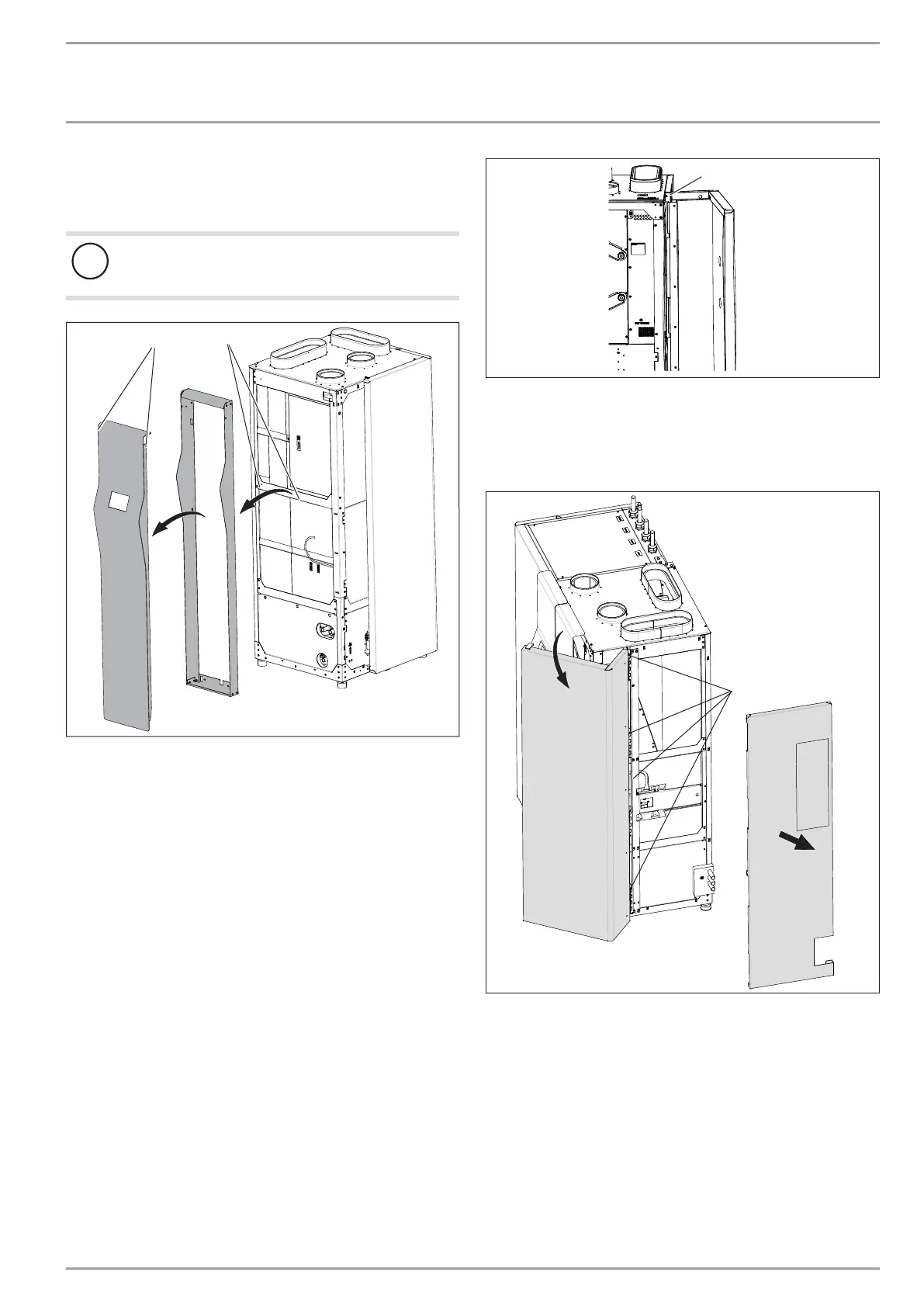
1
2
D0000076586
1 Support screws of the fascia framework
2 Fascia fixing screws
The fascia and fascia frame that are fitted to the front of the ap-
pliance later, hang for shipping from the factory on the l.h. side
of the function module.
Lift the fascia frame slightly and remove the fascia from the
function module.
Undo both support screws from which the fascia was hung
from the lateral cross bar of the function module. If these
support screws are not removed they would be in the way
when pushing the function and cylinder modules together
and securing them with screws. Put the support screws aside
and use one of these later to secure the fascia frame to the
appliance.
Undo both lateral fascia fixing screws with which it is secu-
red to the fascia frame.
Pull the fascia slightly upwards and then forwards out of the
fascia frame.
Remove the wooden braces secured to the pallet which pre-
vented the appliance from slipping during shipping.
Open the function module door.
D0000046700
1
1 Fixing screw on the r.h. side panel
At the top of the gap between door and appliance, undo the
fixing screw for the r.h. side panel.
Carefully push the the r.h. side panel up and remove the side
panel from the appliance.
D0000038984
1
1 Fixing screws of the door
Undo the fixing screws of the door.
Remove the door.
Remove the function module carefully from the pallet.
Push the sliding blocks supplied under the adjustable feet, so
the function module can be moved more easily to the requi-
red position.
Remove the sliding blocks once the appliance is in its inten-
ded location.

 Loading...


