5
With the menu item ROOM TEMP 1 you can select the SET ROOM TEMP for day and setback mode
for heating circuit 1.
The actual room temperature can also be scanned, as soon as the FE 7 or FEK remote control has
been connected and allocated to heating circuit 1.
With the menu item ROOM TEMP 2 you can select the SET ROOM TEMP for day and setback mode
for heating circuit 2. ROOM TEMP 2 will only be displayed, if the mixer flow sensor for heating cir-
cuit 2 has been connected.
The actual room temperature can also be scanned, as soon as the FE 7 or FEK remote control has
been connected and allocated to heating circuit 2.
You can allocate a set day or night temperature to the DHW cylinder temperature using the
menu item DHW TEMP
You can adjust the time and summer time with the TIME/DATE menu item.
At the factory, summer time is set up to begin on the 25 March and to end on the 25 October.
The HOLIDAY PROG menu item puts the heat pump system into setback mode. Frost protection is
activated for the DHW cylinder.
The PARTY PROG menu item allows you to extend the day mode by a few hours.
The HTG CURVE menu item enables you to adjust one heating curve each for heating circuit 1 and
2. The room temperature will only remain constant, irrespective of the outside temperature, if the
correct heating curve has been selected for the relevant type of building. Selecting the correct
heating curve is therefore vitally important.
The HTG PROG menu item enables you to adjust associated heating programs for heating circuit 1
and 2 respectively.
The DHW PROG menu item enables you to adjust the times for the day and setback temperatures
for DHW HTG.
The menu item INFO TEMP enables you to scan the heat pump or heat pump system sensor tem-
peratures, comparing set with actual values, the heating curve gap, etc.
As part of the commissioning process, determine not only the adjustments at control level 2 but
also the system-specific parameters. These parameters are adjusted at control level 3, access to
which is protected by code.
Check all parameters in sequence.
Enter all selected values into the column (system value) provided on the commissioning report.
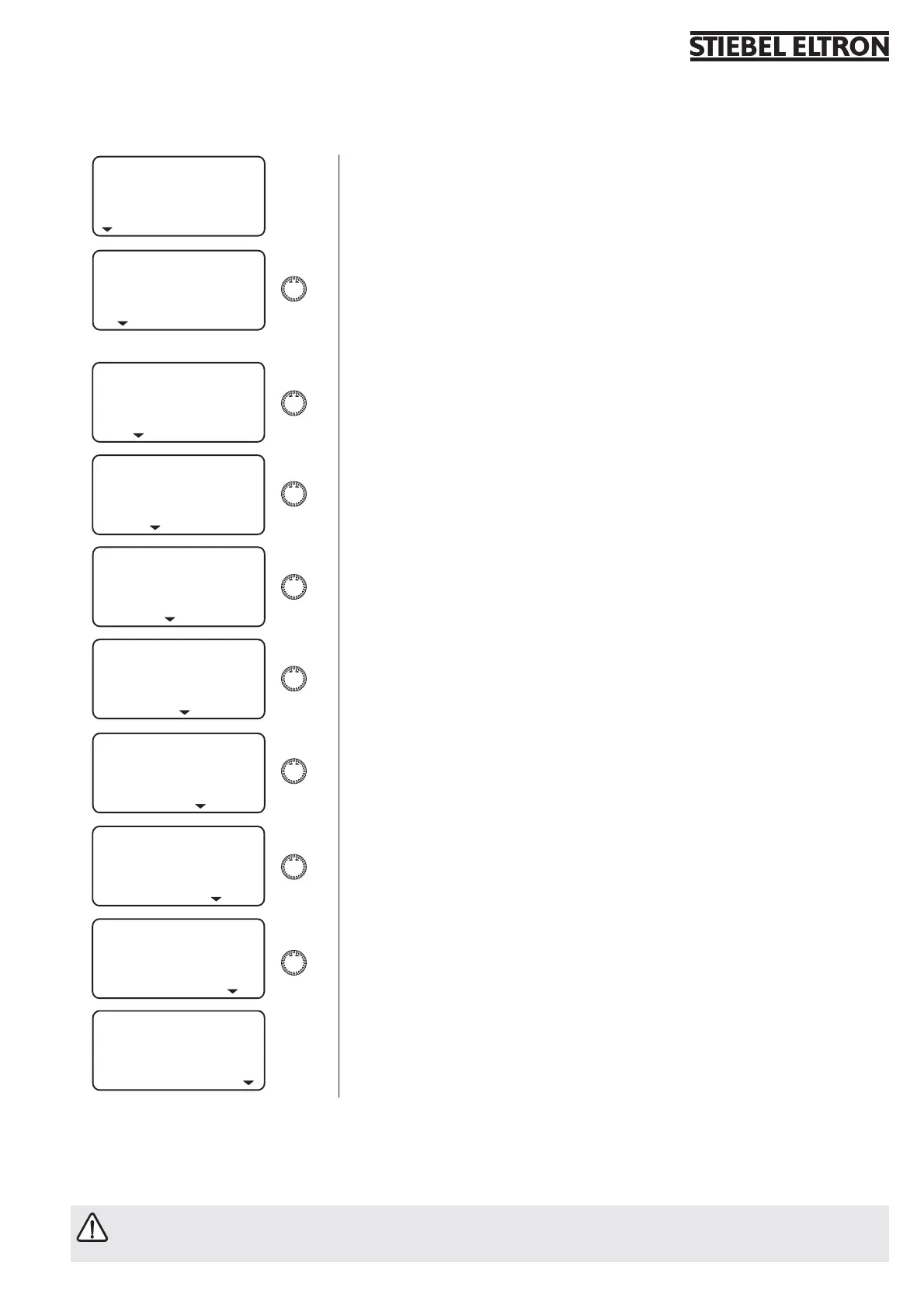
1.8.2 Overview of system parameters (control level 2)
Select the required menu point with the rotary selector.
For adjustments to menu items, turn to page 6.
Room t HC1
Room t HC2
DHW TEMP
Time / Date
Hol / Party
Temperatures
hTG cURVES
hTG Prog
dHw Prog
START UP
1.8.3 In case of the WPF with WPAC 1, the room temperature for the cooling mode is set up by your contractor at control level 3. Cooling is activated,
when the room temperature is higher than the set room temperature. The cooling mode terminates, when the actual room temperature is 2 K < the
set room temperature.
For cooling via cooling surfaces (underfloor heating/wall area heating systems), you need the additional FEK remote control (part. no. 22 01
93). For cooling via fan convectors, you need the additional FEK remote control (part no. 22 01 93). Cooling via radiators would result in moi-
sture damage; it is therefore not permissible.

 Loading...


